
Page 196 - Analog and Digital Filter Design
P. 196
Bandpass Filters 19
R3
I output
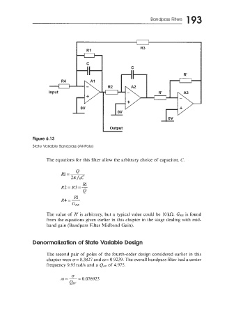
Figure 6.13
State Variable Bandpass (All-Pole)
The equations for this filter allow the arbitrary choice of capacitor, C.
Rl
R2=R3=-
Q
Rl
R4 =-
GRR
The value of R’ is arbitrary, but a typical value could be 10 kR. GRR is found
from the equations given earlier in this chapter in the stage dealing with mid-
band gain (Bandpass Filter Midband Gain).
Denorrnaliration of State Variable Design
The second pair of poles of the fourth-order design considered earlier in this
chapter were G= 0.3827 and o= 0.9239. The overall bandpass filter had a center
frequency 9.95radts and a QRp of 4.975.
0.
171 = - 0.076925
=
QRP