
Page 199 - Analog and Digital Filter Design
P. 199
1 96 Analog and Digital Filter Design
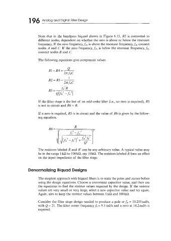
Note that in the bandpass biquad shown in Figure 6.15, R5 is connected to
different nodes, dependent on whether the zero is above or below the resonant
frequency. If the zero frequency, fz, is above the resonant frequency, fR, connect
nodes A and C. If the zero frequency, fi, is below the resonant frequency, fR,
connect nodes B and C.
The following equations give component values.
If the filter stage is the last of an odd-order filter (i.e., no zero is required), R5
is not in circuit and R6 = R.
If a zero is required, R5 is in circuit and the value of R6 is given by the follow-
ing equation.
R
16= ,
The resistors labeled R and R' can be any arbitrary value. A typical value may
be in the range 1 kR to 100 k!2, say 10 kR. The resistors labeled R have an effect
on the input impedance of the filter stage.
Denormalizing Biquad Designs
The simplest approach with biquad filters is to scale the poles and zeroes before
using the design equations. Choose a convenient capacitor value, and then use
the equations to find the resistor values required by the design. If the resistor
values are very small or very large, select a new capacitor value and try again.
Again, aim to keep the resistor values between 1162 and 100kR.
Consider the Bter stage design needed to produce a pole at fR = 10.255rad/s,
with Q = 21. The filter center frequency& = 9.1 rad/s and a zero at 14.2rads is
required.