
Page 203 - Analog and Digital Filter Design
P. 203
200 Analog and Digital Filter Design
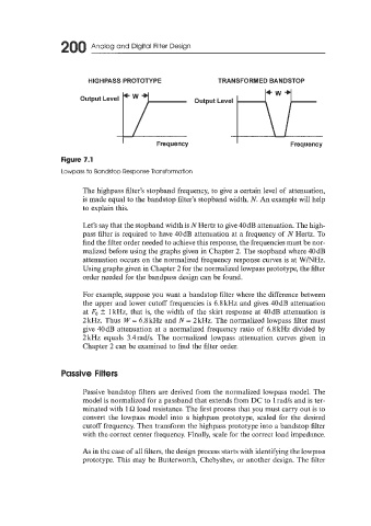
HIGHPASS PROTOTYPE TRANSFORMED BANDSTOP
I Frequency I Frequency
Figure 7.1
Lowpass to Bandstop Response Transformation
The highpass filter’s stopband frequency, to give a certain level of attenuation,
is made equal to the bandstop filter’s stopband width, N. An example will help
to explain this.
Let’s say that the stopband width is NHertz to give 40dB attenuation. The high-
pass filter is required to have 40dB attenuation at a frequency of N Hertz. To
find the filter order needed to achieve this response, the frequencies must be nor-
malized before using the graphs given in Chapter 2. The stopband where 40dB
attenuation occurs on the normalized frequency response curves is at W/NHz.
Using graphs given in Chapter 2 for the normalized lowpass prototype, the filter
order needed for the bandpass design can be found.
For example, suppose you want a bandstop filter where the difference between
the upper and lower cutoff frequencies is 6.8kHz and gives 40dB attenuation
at Fo k 1 kHz, that is, the width of the skirt response at 40dB attenuation is
2 kHz. Thus W = 6.8 kHz and N = 2 kHz. The normalized lowpass filter must
give 40dB attenuation at a normalized frequency ratio of 6.8kHz divided by
2 kHz equals 3.4rads. The normalized lowpass attenuation curves given in
Chapter 2 can be examined to find the filter order.
Passive Filters
Passive bandstop filters are derived from the normalized lowpass model. The
model is normalized for a passband that extends from DC to 1 rad/s and is ter-
minated with 1 Q load resistance. The first process that you must carry out is to
convert the lowpass model into a highpass prototype, scaled for the desired
cutoff frequency. Then transform the highpass prototype into a bandstop filter
with the correct center frequency. Finally, scale for the correct load impedance.
As in the case of all filters, the design process starts with identifying the lowpass
prototype. This may be Butterworth, Chebyshev, or another design. The filter