
Page 204 - Analog and Digital Filter Design
P. 204
Bandstop Filters 20 1
order must also be determined. Suppose you need a filter with a 2.4 kHz band-
width between the 3dB points and with 40dB attenuation at +250Hz (a 500Hz
stopband width). In addition the circuit is required to have a center frequency,
fi,. of 320kHz. Design a Butterworth bandstop filter that achieves this
specification.
Passband to stopband ratio = 2.4/0.5 = 4.8. Referring to the normalized
responses in Chapter 2, a third-order filter will just about achieve the required
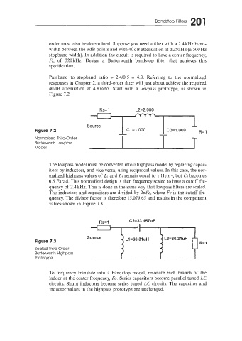
40dB attenuation at 4.8radls. Start with a lowpass prototype, as shown in
Figure 7.2.
Rs=l L2=2.000
Figure 7.2
Normalized Third-Order
Butterworth Lowpass
Model
The lowpass model must be converted into a highpass model by replacing capac-
itors by inductors, and vice versa, using reciprocal values. In this case, the nor-
malized highpass values of LI and L3 remain equal to 1 Henry, but Cz becomes
0.5 Farad. This normalized design is then frequency scaled to have a cutoff fre-
quency of 3.4kHz. This is done in the same way that lowpass filters are scaled.
The inductors and capacitors are divided by 2nFc, where Fc is the cutoff fre-
quency. The divisor factor is therefore 15,079.65 and results in the component
values shown in Figure 7.3.
Rs=l C2=33.157uF
Figure 7.3 R=l
Scaled Third-Order
Butterworth Highpass
Prototype
To frequency translate into a bandstop model, resonate each branch of the
ladder at the center frequency, Fo. Series capacitors become parallel tuned LC
circuits. Shunt inductors become series tuned LC circuits. The capacitor and
inductor values in the highpass prototype are unchanged.