
Page 209 - Analog and Digital Filter Design
P. 209
206 Analog and Digital Filter Design
placed symmetrically either side of the center frequency. Even-order filters just
have zeroes at stopband frequencies, symmetrically placed around the center. As
you would expect, the circuit topologies of Cauer and Inverse Chebyshev filters
are more complex. Their circuits are sinlilar to those described for bandpass
filters.
I have shown in earlier chapters that designing for lowpass or highpass Cauer
filters is straightforward. Lowpass filter zeroes are scaled outward from the S-
plane origin. Highpass filter zeroes are inverted, and then they are scaled to be
in the stopband. Zeroes in the resultant passive filter are produced by parallel
resonant circuits in the series arm or series resonant circuits in the shunt arm.
Cauer and Inverse Chebyshev lowpass responses both have zeroes in the stop-
band and at infinity. During transformation into a bandstop filter, these zeroes
change location. Zeroes at infinity in the lowpass filter’s S-plane diagram move
to the center of the stopband, just like those of all-pole filters. Zeroes in the
lowpass filter’s stopband become two zeroes in the bandstop filter’s S-plane
diagram. These are placed symmetrically about the stopband center frequency.
Physically each zero becomes a resonant circuit tuned to the zero’s frequency.
In the lowpass prototype a zero is produced by a parallel resonant circuit in the
series arm. However, one zero in the lowpass prototype became two zeroes in
the bandstop filter. Therefore, each resonant circuit in the series arm of the
lowpass prototype becomes two resonant circuits in the bandstop filter. The two
resonant circuits are connected in series and form a single arm of the filter. Each
one resonates at a different frequency, one above and one below the stopband
center frequency.
The first action in designing the bandstop filter is to take the required lowpass
prototype and convert it into a highpass prototype. This must then be scaled
by the bandpass Q factor before being converted into a normalized bandpass
prototype. The parallel resonant series arms are then transformed into dual
parallel resonant networks. These will create two stopband zeroes in the final
frequency response. Frequency and impedance scaling are then used to find the
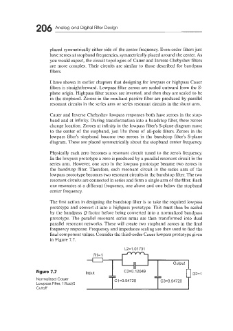
final component values. Consider the third-order Cauer lowpass prototype given
in Figure 7.7.
L2=1.01731
II output
Figure 7.7 Input -- C2=0.12049 -- R2= 1
--
--
Normalized Cauer C1=0.94720 C3=0.94720
Lowpass Filter, 1 Rad/S
cutoff