
Page 210 - Analog and Digital Filter Design
P. 210
Bandstop Filters 207
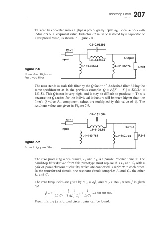
This can be converted into a highpass prototype by replacing the capacitors with
inductors of a reciprocal value. Inductor L2 must be replaced by a capacitor of
a reciprocal value, as shown in Figure 7.8.
62=0.98298
Figure 7.8
Normalized Highpass
Prototype Filler
The next step is to scale this filter by the Q factor of the desired filter. Using the
same specification as in the previous example, Q = E,/[FL - FL] = 32012.4 =
133.33. This Q factor is very high, and it may be difficult to produce it. This is
because the Q needed for the individual inductors will be much higher than ihe
filter's Q value. All component values are multiplied by this value of Q. The
resultant values are given in Figure 7.9.
C2=131.064
Rl =I
Figure 7.9
Scaied Highpass Filter 1 f I
The zero producing series branch, L2 and C2, is a parallel resonant circuit. The
bandstop filter derived from this prototype must replace this L2 and C, with a
pair of parallel resonant circuits, which are connected in series with each other.
In the transformed circuit, one resonant circuit comprises L, and C,,, the other
L,, and C,,.
The zero frequencies are given by m-', = @, and c0-h = l/mw,, where p is given
by:
From this the transformed circuit pairs can be found: