
Page 222 - Analog and Digital Filter Design
P. 222
Bandstop Filters 2 1 9
The value of R’ is discretionary, but a typical value could be 10 kQ. Resistors R
also have an arbitrary value that could be set the same as R’ if required. Note
that the value of R has an effect on the filter’s input impedance.
Denormalization of Bandstop State Variable Filter Section
Consider one pole found earlier for the fourth-order Butterworth 50 Hz notch
filter. For this polef, = 44.59091 Hz or 280.17295rad/s, having Q = 13.1206264.
Let C = 0.1 pF and let R = R’ = 10 kQ.
Cauer and Inverse Chebyshev Active Filters
Designing bandstop filters with a Cauer or an Inverse Chebyshev response is
more difficult than for all-pole filters. This is because each filter section must
provide both poles and zeroes close to the filter’s center frequency. Moreover,
the pole and zero pairing must also be considered. A filter may have a number
of poles and zeroes and, in principle, any zero could be associated with any pole.
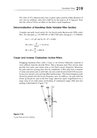
In practice, the pole-zero pairing affects performance. The lowest frequency pole
should be paired with the lowest frequency zero. In addition, the pole with the
lowest Q should be used in the first stage, otherwise signal magnification by a
large value of Q could cause overloading of subsequent stages. Pole and zero
pairing is illustrated in Figure 7.16.
Figure 7.14
Cauer Poie and Zero Pairing