
Page 221 - Analog and Digital Filter Design
P. 221
2 1 8 Analog and Digital Filter Design
For this pole fR = 51.456284Hz or 323.3093676rad/s, having Q = 5.361447.
Let C= O-lpF and let R= R"= low.
R1 = Q.R2 = 26,393Q.
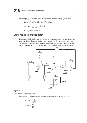
State Variable Bandstop Filters
The state variable design can be used for all-pole responses, or in any filter where
a zero at the stopband center frequency is required. It has a lower sensitivity to
the op-amp's gain-bandwidth product limitation, and section Q factors of up to
200 are possible. It does, however, need four op-amps, as shown in Figure 7.15.
R3
Rl
Figure 7.15
State Variable Bandstop (All-Pole)
The equations for this filter allow the arbitrary choice of capacitor, C.
R1
R2 = R3 = -
Q