
Page 216 - Analog and Digital Filter Design
P. 216
Bandstop Filters 2
Taking a look at some bandstop active filter designs, I will show how the pole
and zero locations are used to find component values. We will return to the S-
plane later in this chapter when discussing active Cauer and Inverse Chebyshev
filters. Both these types have zeroes in the stopband that are not at the cecter
frequency.
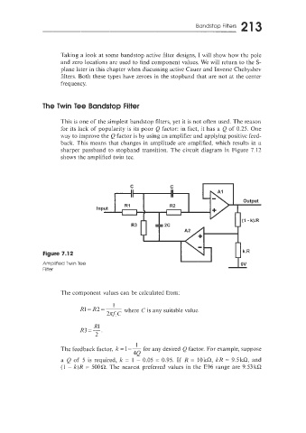
The Twin Tee Bandstop Filter
This is one of the simplest bandstop filters, yet it is not often used. The reason
for its Iack of popularity is its poor Q factor: in fact, it has a Q of 0.25. One
way to improve the Q factor is by using an amplifier and applying positive feed-
back. This means that changes in amplitude are amplified. which results in a
sharper passband to stopband transition. The circuit diagram in Figure 7.12
shows the amplified twin tee.
n
C C
Figure 7.12
Amplified Twin Tee
Filter
The component values can be calculated from:
1
R1= R2 =- where C is any suitable value.
2E”f:C
R1
R3=-.
2
1
The feedback factor, k = 1 - - for any desired Q factor. For example, suppose
4Q
a Q of 5 is required, k = 1 - 0.05 = 0.95. If R = 10kQ kR = 9.5kC2, and
(1 - k)R = 500Q. The nearest preferred values in the E96 range are 9.53kQ