
Page 218 - Analog and Digital Filter Design
P. 218
2
Bandstop Filters
R
I
C2
I
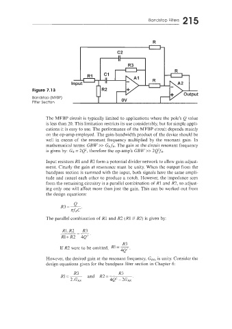
Figure 7.13
Bandstop (MFBP)
Filter Section
The MFBP circuit is typically limited to applications where the pole’s Q value
is less than 20. This limitation restricts its use considerably, but for simple appli-
cations it is easy to use. The performance of the MFBP circuit depends nainly
on the op-amp employed. The gain-bandwidth product of the device should be
well in excess of the resonant frequency multiplied by the resonant gain. In
mathematical terms: GBW >> GR.fR. The gain at the circuit resonant frequency
is given by: GR = 2Q2, therefore the op-amp’s GBW‘>> 2(2TfR.
‘Input resistors R1 and R2 form a potential divider network to allow gain adjust-
ment. Clearly the gain at resonance must be unity. When the output from the
bandpass section is summed with the input, both signals have the same arnpii-
tude and cancel each other to produce a notch. However, the impedance seen
from the remaining circuitry is a parallel Combination of R1 and R2, so adjust-
ing only one will affect more than just the gain. This can be worked out from
the design equations:
The parallel combination of R1 and R3 (R1 /I R2) is given by:
Rl.R2 R3
-
R1-tR2 4Q”
R3
If R2 were to be omitted, R1=*.
However, the desired gain at the resonant frequency, GRR, is unity. Consider the
design equations given for the bandpass filter section in Chapter 6: