
Page 322 - Analog and Digital Filter Design
P. 322
319
Transmission Lines and Printed Circuit Boards as Filters
A similar equation exists for capacitors:
In this foimula is the relative effective permitivity (= 4.24) of the dielectric
for a 25mm wide line. The impedance of this line is given by Z,,, = 9.663.
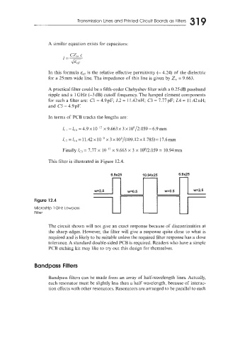
A practical filter could be a fifth-order Chebyshev filter with a 0.25 dB passband
ripple and a 1 GHz (-3 dB) cutoff frequency. The lumped element components
for such a filter are: C1 = 4.9 pF; L2 = 1 1.42 nH; C3 = 7.77 pF; L4 = 1 1.42 nH;
and C5 = 4.9pF.
In terms of PCB tracks the lengths are:
lcl = lc5 = 4.9 x lo-'' x 9.663 x 3 x 108/2.059 = 6.9 mm
lL2 =IL4 = 11.42 x x 3 x 10'/(109.12 x 1.785)= 17.6m
Finally IC3 = 7.77 x IO-'' x 9.663 x 3 x 108/2.059 = 10.94mm
This filter is illustrated in Figure 12.4.
Figure 12.4
Microstrip 1 GHz Lowpass
Filter
The circuit shown will not give an exact response because of discontinuities at
the sharp edges. However, the filter will give a response quite close to what is
required and is likely to be suitable unless the required filter response has a close
tolerance. A standard double-sided PCB is required. Readers who have a simple
PCB etching kit may like to try out this design for themselves.
Bandpass Filters
Bandpass filters can be made from an array of half-wavelength lines. Actually,
each resonator must be slightly less than a half wavelength, because of interac-
tion effects with other resonators. Resonators are arranged to be parallel to each