
Page 324 - Analog and Digital Filter Design
P. 324
13
CHAPTER
FILTERS FOR PHASE-LOCKED LOOPS
Filters for phase-locked loops are usually quite simple. Poor design of the loop
filter can cause overall instability of the loop. Many people avoid designing
phase-locked loops for this reason. Here I give some examples and explanations
that should help to remove some of this fear. This chapter can only be inbro-
ductory: whole books have been devoted to this subject.’
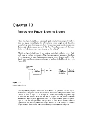
What is a phase-locked loop? It is a voltage-controlled oscillator with a feed-
back loop to a phase comparator. The phase comparator compares the phase
of two signals on its input; in ths case, one signal is the reference and the other
signal is the oscillator output. A diagram of a phase-locked loop is shown in
Figure 13.1.
Reference
InP
Figure 13.1
Phase-Locked Loop
The simplest digital phase detector is an exclusive-OR gate that has two inputs.
If the two input signals are 90” out-of-phase, the output voltage spends the same
amount of time at logic ”1” as at logic “0.” Hence, the average output voltage
is equal to the midrail point of the power supply. As the phase difference
between the input signals approaches zero, the output voltage spends longer at
logic “0” and the average output voltage tends to zero. As the phase difference
approaches 180”. the output spends longer at logic .‘I” than at logic “0” and the
output voltage tends to 5 V (or whatever the positive supply voltage is).