
Page 329 - Analog and Digital Filter Design
P. 329
326 Analog and Digital Filter Design
R2
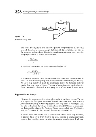
Figure 13.5
ov
Active Lead-Lag Filter
The active lead-lag filter uses the same passive components as the lead-lag
network described previously, except that some of the components are now in
the op-amp’s feedback loop. The design equations are the same apart from the
damping coefficient, 5, which is now simpler.
r= R2. C .O ,v
The transfer function of the active loop filter is given by:
R2.C.s + 1
F(s) =
R1.C.s ’
If damping is reduced to zero, the phase-locked loop becomes a sinusoidal oscil-
lator. The oscillation frequency is o,~, which is the natural frequency of the loop.
An input step signal will start the oscillations, but if the damping factor is
greater than zero these will decay. The rate of decay is greater as the damping
factor increases in value until, at a damping factor of one, no oscillations occur.
H ig her-Order loops
Higher-order loops are used to reduce phase noise in oscillator circuits. The use
of a high-order filter gives a narrower bandwidth for feedback, thus reducing
jitter in the frequency of the output signal. The loop order is one higher than
the filter order, since the voltage-controlled oscillator (VCO) acts as an integra-
tor that provides a first-order function. Thus a phase-locked loop (PLL) using
a simple first-order RC filter network forms a second-order loop.
A second-order filter can be used to form part of a third-order loop. However,
in practice third-order filters tend to be used, creating a fourth-order loop,
because they provide greater reduction in spurious signal output. I will now