
Page 327 - Analog and Digital Filter Design
P. 327
324 Analog and Digital Filter Design
loop Filters
In both frequency multiplier and FM signal demodulator applications, the
purpose of the loop filter is to average the phase detector output voltage. It must
do this while allowing the system to respond to changes in the reference signal’s
frequency. The phase detector will output some spurious signals at the reference
frequency. The filter must remove these signals before they reach the oscillator.
Otherwise the oscillator will be modulated unnecessarily and produce jitter at
its output. The loop filter is thus a critical part of the phase-locked loop circuit.
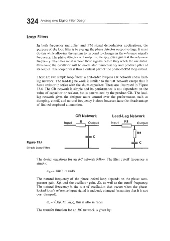
There are two simple loop filters: a first-order lowpass CR network and a lead-
lag network. The lead-lag network is similar to the CR network except that it
has a resistor in series with the shunt capacitor. These are illustrated in Figure
13.4. The CR network is simple and its performance is not dependent on the
value of capacitor or resistor, but is determined by the product CR. The lead-
lag network gives the designer more control over the Performance, such as
damping, cutoff, and natural frequency. It does, however, have the disadvantage
of limited stopband attenuation.
CR Network Lead-Lag Network
R
Figure 13.4
Simple Loop Filters
The design equations for an RC network follow. The filter cutoff frequency is
simply:
wLp = lIRC, in rads
The natural frequency of the phase-locked loop depends on the phase com-
parator gain, K$, and the oscillator gain, KO, as well as the cutoff frequency.
The natural frequency is the rate of oscillation that occurs when the phase-
locked loop’s reference input signal is suddenly changed (assuming that it is not
over damped):
m,? = d(K$. KO. mLd, this is also in radls.
The transfer function for an RC network is given by: