
Page 326 - Analog and Digital Filter Design
P. 326
Filters for Phase-Locked Loops 323
Demodulated
FM Output
Frequency
Modulated
Reference
Input
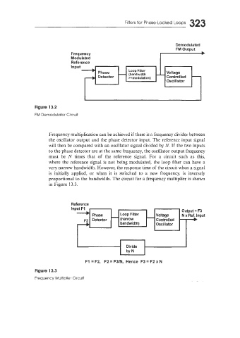
Figure 13.2
FM Demodulator Circuit
Frequency multiplication can be achieved if there is a frequency divider between
the oscillator output and the phase detector input. The reference input signal
will then be compared with an oscillator signal divided by N. If the two inputs
to the phase detector are at the same frequency, the oscillator output frequency
must be N times that of the reference signal. For a circuit such as this,
where the reference signal is not being modulated, the loop filter can have a
very narrow bandwidth. However, the response time of the circuit when a signal
is initially applied, or when it is switched to a new frequency, is inversely
proportional to the bandwidth. The circuit for a frequency multiplier is shown
in Figure 13.3.
Reference
InP
F1 = F2, F2 = F3/N, Hence F3 = F2 x N
Figure 13.3
Frequency Multiplier Circuit