
Page 323 - Analog and Digital Filter Design
P. 323
320 Analog and Digital Filter Design
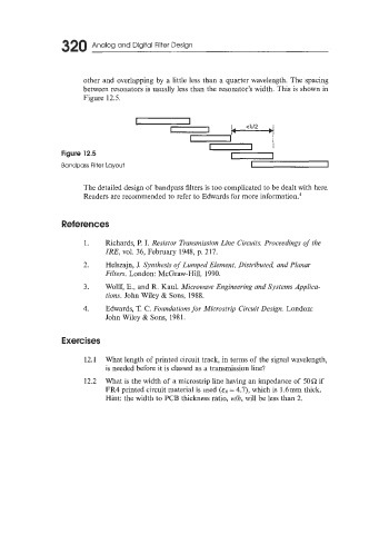
other and overlapping by a little less than a quarter wavelength. The spacing
between resonators is usually less than the resonator’s width, This is shown in
Figure 12.5.
Figure 12.5
Bandpass Filter Layout
The detailed design of bandpass filters is too complicated to be dealt with here.
Readers are recommended to refer to Edwards for more information.4
References
1. Richards, P. I. Resistor Transmission Line Circuits. Proceedings of the
IRE, vol. 36, February 1948, p. 217.
2. Helszajn, J. Synthesis of Lumped Element, Distributed, and Planar
FiIters. London: McGraw-Hill, 1990.
3. Wolff, E., and R. Kaul. Microwave Engineering and Systems Applica-
tions. John Wiley & Sons, 1988.
4. Edwards, T. C. Foundations for Microstrip Circuit Design. London:
John Wiley & Sons, 1981.
Exercises
12.1 What length of printed circuit track, in terms of the signal wavelength,
is needed before it is classed as a transmission line?
12.2 What is the width of a microstrip line having an impedance of 50Q if
FR4 printed circuit material is used (E~ 4.7), which is 1.6mm thick.
=
Hint: the width to PCB thickness ratio, wlh, will be less than 2.