
Page 330 - Analog and Digital Filter Design
P. 330
327
Filters for Phase-Locked Loops
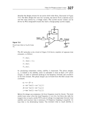
describe the design process for an active third-order filter, illustrated in Figure
13.6. The filter design will have two variants, one driven from a current source
and the other driven by a voltage source. The current source variant can be
driven by PLL integrated circuits that have a charge-pump current output.
c2
Figure 13.6
Third-Order Filter for Fourth-Order
PLL
The RC networks in the circuit of Figure 13.6 form a number of separate time
constants, as follows:
In calculating component values, stability is important. The phase margin,
q,,,,, is related to the stability, and it is advisable to have at least a 45" phase
margin, in order to minimize peaking in the frequency domain and overshoot
in the time domain. The phase margin can be found from the filter circuit time
constants:
Before the design can commence, the loop frequency must be chosen. The most
stable loops occur when the loop frequency is very low, but these also take the
iongest time to reach a stable VCO control voltage. A compromise between loop
stability and reaction time is necessary. If frequency hopping is required, the
hop time is the dominating feature. The transient time to reach stability is