
Page 334 - Analog and Digital Filter Design
P. 334
33 1
Filters for Phase-Locked Loops
terms do not cancel and finding a solution is more difficult: another good
(pragmatic) reason for choosing j = l/a.
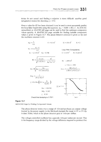
Once a value for R2 has been obtained it can be used to more accurately predict
the loop filter bandwidth using the equation: wLp = lI(R1 + R2). G. An EXCEL
spreadsheet or MATHCAD page can be used to find the optimum component
values quickly. A MATHCAD page suitable for finding suitable component
values is given in Figure 13.7. The phase detector constant is given as Kp and
the oscillator constant is KY.
Loop Filter Components
s :=O.L,l.. 1000
i KV F(s) = R2.s C+ 1
U'n Kp N.C.( RI + R2) s.( R 1.C + R2.C) + 1
WIp = I
(R1 + R2).C
Wn = 13S.518
Wlp = 0.307
I I i
< = 0.707 1 I/ 2 4
Check that damping is 0.707: log( 5 1
Figure 13.7
MATHC4D Page for Finding Component Values
The phase detector works over a range of k27c and produces an output voltage
limited by the power supply: in the Mathcad example the range is OV to 5 V. Kp
is then 5444, which is the phase detector gain in volts per radian.
The voltage-controlled oscillator has a gain KO volts per radian per second. This
is the frequency range divided by the voltage difference required to produce that