
Page 68 - Analog and Digital Filter Design
P. 68
65
Time and Frequency Response
Equal load Normalized Component Value Tables
Since most passive filters have equal source and load impedance, the normal-
ized values for these are given in Tables 2.10 to 2.14. Another useful filter is
designed for infinite or zero source impedance, and element values for these are
given in Tables 2.16 to 2.20. For other loads the reader should make use of the
equations given in the Appendix to calculate the required element values. Trans-
formation to any lowpass, highpass, bandpass, or bandstop designs is then pos-
sible. Details will be given in Chapters 4, 5, 6, and 7, respectively.
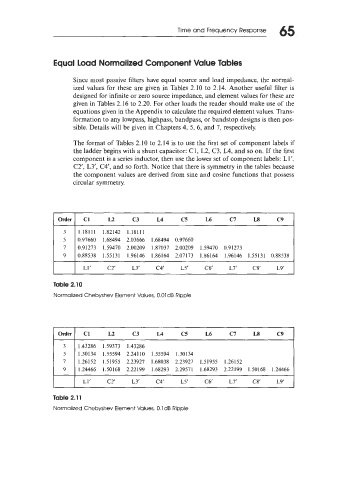
The format of Tables 2.10 to 2.14 is to use the first set of component labels if
the ladder begins with a shunt capacitor: C1, L2, C3, L4, and so on. If the first
component is a series inductor, then use the lower set of component labels: Ll’.
C2’, L3’, C4‘, and so forth. Notice that there is symmetry in the tables because
the component values are derived from sine and cosine functions that possess
circular symmetry.
Order
3 1.18111 1.82142 1.18111
5 0.97660 1.68494 2.03666 1.68494 0.97660
7 0.91273 1.59470 2.00209 1.87037 2.00209 1.59470 0.91273
9 0.88538 1.55131 1.96146 1.86164 2.07173 1.86164 1.96146 1.55131 0.88538
I I L1‘ C2’ L3’ C4’ L5‘ C6‘ L7’ C8’ L9‘ I
Table 2.10
Normalized Chebyshev Element Values, 0.01 dB Ripple
I Order I CI L2 c3 L4 c5 L6 c7 L8 c9 I
1.43286 1.59373 1.43286
1.30134 1.55594 2.24110 1.55594 1.30134
1.26152 1.51955 2.23927 1.68038 2.23927 1.51955 1.26152
1.24466 1.50168 2.22199 1.68293 2.29571 1.68293 2.22199 1.50168 1.24466
L 1’ C2’ L3’ C4‘ L5‘ C6‘ L7‘ C8’ LY
Table 2.1 1
Normalized Chebyshev Element Values, 0.1 dB Ripple