
Page 67 - Analog and Digital Filter Design
P. 67
64 Analog and Digital Filter Design
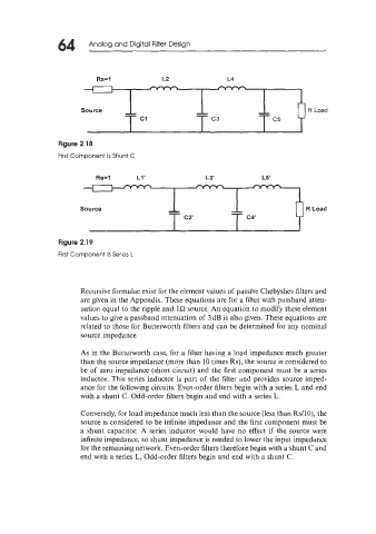
Rs=l L2 L4
Figure 2.18
First Component Is Shunt C
Rs=l L1' L3' L5'
Source
Figure 2.19
First Component Is Series L
Recursive formulae exist for the element values of passive Chebyshev filters and
are given in the Appendix. These equations are for a filter with passband atten-
uation equal to the ripple and 1R source. An equation to modify these element
values to give a passband attenuation of 3dB is also given. These equations are
related to those for Butterworth filters and can be determined for any nominal
source impedance.
As in the Butterworth case, for a filter having a load impedance much greater
than the source impedance (more than 10 times Rs), the source is considered to
be of zero impedance (short circuit) and the first component must be a series
inductor. This series inductor is part of the filter and provides source imped-
ance for the following circuits. Even-order filters begin with a series L and end
with a shunt C. Odd-order filters begin and end with a series L.
Conversely, for load impedance much less than the source (less than Rs/lO), the
source is considered to be infinite impedance and the first component must be
a shunt capacitor. A series inductor would have no effect if the source were
infinite impedance, so shunt impedance is needed to lower the input impedance
for the remaining network. Even-order filters therefore begin with a shunt C and
end with a series L. Odd-order filters begin and end with a shunt C.