
Page 70 - Analog and Digital Filter Design
P. 70
67
Time and Frequency Response
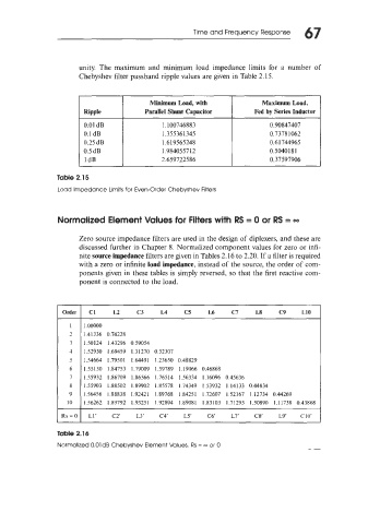
unity. The maximum and minimum load impedance limits for a number of
Chebyshev filter passband ripple values are given in Table 2.15.
Minimum Load, with Maximum Load,
Ripple Parallel Shunt Capacitor Fed by Series Inductor
0.01 dB 1.100746883 0.90847407
0.1 dB 1.355361345 0.73781062
0.25 dB 1,619565248 0.61744965
0.5 dB 1.984055712 0.5040 1 8 1
I 1dB I 2.659722586 1 0.37597906
Table 2.15
Load Impedance Limits for Even-Order Chebyshev Filters
Normalized Element Values for Filters with RS = 0 or RS = 00
Zero source impedance filters are used in the design of diplexers, and these are
discussed further in Chapter 8. Normalized component values for zero or infi-
nite source impedance filters are given in Tables 2.16 to 2.20. If a filter is required
with a zero or infinite load impedance, instead of the source, the order of com-
ponents given in these tables is simply reversed, so that the first reactive com-
ponent is connected to the load.
Order Cl L2 C3 L4 C5 L6 Cl L8 C9 L10
I 1 .ooooo
- 1.41336 0.74228
1
3 1.50124 1.43296 0.59054
4 1.52930 1.69459 1.31270 0.52307
5 1.54664 1.79501 1.64491 1.23650 0.48829
6 1.55130 1.84753 1.79009 1.59789 1.19066 0.46868
7 1.55932 1.86709 1.86566 1.76514 1.56334 1.16096 0.45636
8 1.55903 1.88502 1.89902 1.85578 1.74349 1.53932 1.14133 0.44834
9 1.56456 1.88838 1.92421 1.89768 1.84251 1.72607 1.52167 1.12734 0.44269
IO 1.56262 1.89792 1.93251 1.92894 1.89081 1.83103 1.71295 1.50890 1.11738 0.43868
Rs = 0 LI’ c2’ L3’ c4‘ LS c6‘ L7’ C8’ L9’ C10’
Table 2.16
Normalized O.OldB Chebyshev Element Values, Rs = 00 or 0