
Page 277 - Analysis and Design of Machine Elements
P. 277
Wormgear Drives
2 The worm reference diameter d could not be calculated by _____ ( is lead angle) 255
1
(a) d = mq
1
(b) d = 2a−d
1 z 1 m 2
(c) d =
1 tan
(d) d = mz
1 1
3 In a wormgear drive, not only is the module standardized, but also the reference
diameter of the worm d . The purpose of such regulation is ________.
1
(a) to facilitate assembly
(b) to reduce the number of tools required to fabricate worms
(c) to reduce the number of tools required to fabricate wormgears and to facilitate
the standardization of tools
(d) to improve the precision of manufacturing
4 The purpose of heat balance calculation for a worm gearing is to control temperature
in order to prevent___
(a) the deterioration of lubricants and gluing of the wormgear surface
(b) the decrease of worm mechanical properties
(c) the decrease in transmission efficiency
(d) the annealing of the wormgear
Calculation Questions
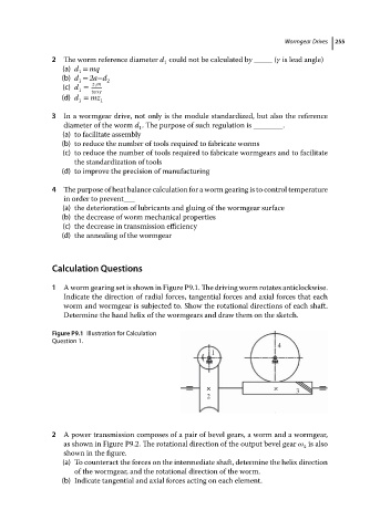
1 A worm gearing set is shown in Figure P9.1. The driving worm rotates anticlockwise.
Indicate the direction of radial forces, tangential forces and axial forces that each
worm and wormgear is subjected to. Show the rotational directions of each shaft.
Determine the hand helix of the wormgears and draw them on the sketch.
Figure P9.1 Illustration for Calculation
Question 1.
4
1
× × 3
2
2 A power transmission composes of a pair of bevel gears, a worm and a wormgear,
as shown in Figure P9.2. The rotational direction of the output bevel gear is also
4
shown in the figure.
(a) To counteract the forces on the intermediate shaft, determine the helix direction
of the wormgear, and the rotational direction of the worm.
(b) Indicate tangential and axial forces acting on each element.