
Page 279 - Analysis and Design of Machine Elements
P. 279
Wormgear Drives
(c) Determine the lead angle of the worm and whether the worm set is self-locking; 257
(d) Calculate the meshing efficiency;
(e) Calculate the forces acting on the wormgear;
(f) Calculate sliding velocity between worm and wormgear;
(g) Determine the power delivered to the lift.
Design Problems
1 A double-threaded steel worm rotates at 1460 rpm, meshing with a 53-tooth wor-
mgear transmitting 20 kW to the output shaft. The wormgear drive works 8 h a day
steadily for 10 years. Design the wormgear drive.
2 A double-threaded steel worm with a module of m = 6.3 mm rotates at 1460 rpm,
meshing with a 53-tooth wormgear. The worm is hardened steel and the gear is
sand-cast bronze. The wormgear set works steadily 8 h a day for 10 years. Decide
the maximum power to be transmitted by the wormgear drive.
3 A wormgear drive is utilized to reduce the speed of a 1460 rpm motor driving the
worm down to an output wormgear shaft speed of approximately 100 rpm and pro-
vides 7.5 kW power to the driven machine. The application factor is 1.25. Design a
wormgear drive and specify the nominal required power rating of the driving motor.
4 Three designs, that is, using a single-thread worm, a double-thread worm and a
four-thread worm, are proposed for a wormgear drive to produce a speed ratio of 20
when the wormgear rotates at 90 rpm. Worms in all the three designs have a module
of 5 mm, and a worm reference diameter of 50 mm. The worms are hardened steel
and the wormgears are chilled bronze. Compare these designs and compute the rated
output torque, satisfying both bending strength and pitting resistance requirements.
Structure Design Problems
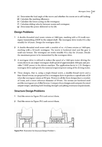
1 Find theerrorsinFigureP9.4and correctthem.
2 Find theerrorsinFigureP9.5and correctthem.
Figure P9.4 Illustration for Structure Design Problem 1.