
Page 278 - Analysis and Design of Machine Elements
P. 278
Analysis and Design of Machine Elements
256
Output shaft Figure P9.2 Illustration for Calculation Question 2.
2 × 4
× ω 4
3
Input shaft
1
3 Awormgearwith41teeth andmoduleof m = 5 mm mates with a double-threaded
worm with a diameter of d = 50 mm. Assume the coefficient of friction is f = 0.1.
1
Determine (1) speed ratio, (2) diameter of wormgear, (3) centre distance, (4) lead
angle of the worm and whether the wormset is self-locking and (5) efficiency.
4 The input power for a wormgear reducer is P = 3 kWwithatotalefficiencyof = 0.8.
2
The heat dissipation area is 1 m and heat transfer coefficient is = 15 W m −2 ∘ C.
s
∘
Assume the ambient temperature is 20 C. It is required that the oil temperature
∘
does not exceed 80 C at heat balance. Please check whether the lubricant oil sump
temperature meets the requirements.
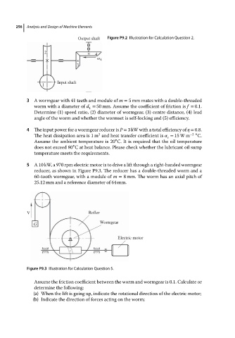
5 A 10 kW, a 970 rpm electric motor is to drive a lift through a right-handed wormgear
reducer, as shown in Figure P9.3. The reducer has a double-threaded worm and a
60-tooth wormgear, with a module of m = 8 mm. The worm hasanaxial pitchof
25.12 mm and a reference diameter of 64 mm.
V Roller
G Wormgear
Electric motor
Figure P9.3 Illustration for Calculation Question 5.
Assume the friction coefficient between the worm and wormgear is 0.1. Calculate or
determine the following:
(a) When the lift is going up, indicate the rotational direction of the electric motor;
(b) Indicate the direction of forces acting on the worm;