
Page 334 - Analysis and Design of Machine Elements
P. 334
Analysis and Design of Machine Elements
312
Figure 11.12 Bearing disassembly.
(a) (b)
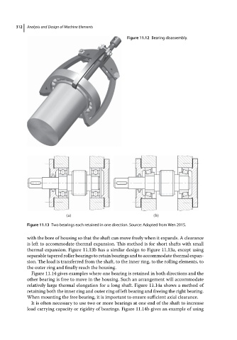
Figure 11.13 Two bearings each retained in one direction. Source: Adapted from Wen 2015.
with the bore of housing so that the shaft can move freely when it expands. A clearance
is left to accommodate thermal expansion. This method is for short shafts with small
thermal expansion. Figure 11.13b has a similar design to Figure 11.13a, except using
separable tapered roller bearings to retain bearings and to accommodate thermal expan-
sion. The load is transferred from the shaft, to the inner ring, to the rolling elements, to
the outer ring and finally reach the housing.
Figure 11.14 gives examples where one bearing is retained in both directions and the
other bearing is free to move in the housing. Such an arrangement will accommodate
relatively large thermal elongation for a long shaft. Figure 11.14a shows a method of
retaining both the inner ring and outer ring of left bearing and freeing the right bearing.
When mounting the free bearing, it is important to ensure sufficient axial clearance.
It is often necessary to use two or more bearings at one end of the shaft to increase
load carrying capacity or rigidity of bearings. Figure 11.14b gives an example of using