
Page 335 - Analysis and Design of Machine Elements
P. 335
(a) (b) Rolling Contact Bearings 313
Figure 11.14 One bearing retained in two directions, one bearing floats.
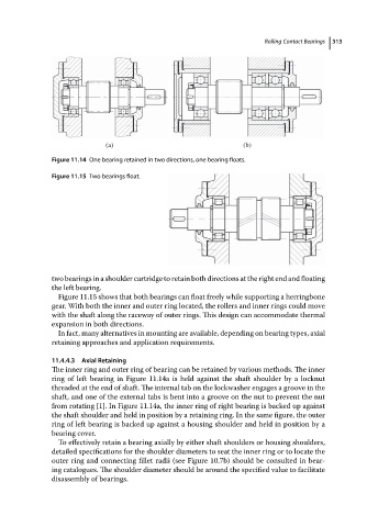
Figure 11.15 Two bearings float.
two bearings in a shoulder cartridge to retain both directions at the right end and floating
the left bearing.
Figure 11.15 shows that both bearings can float freely while supporting a herringbone
gear. With both the inner and outer ring located, the rollers and inner rings could move
with the shaft along the raceway of outer rings. This design can accommodate thermal
expansion in both directions.
In fact, many alternatives in mounting are available, depending on bearing types, axial
retaining approaches and application requirements.
11.4.4.3 Axial Retaining
The inner ring and outer ring of bearing can be retained by various methods. The inner
ring of left bearing in Figure 11.14a is held against the shaft shoulder by a locknut
threaded at the end of shaft. The internal tab on the lockwasher engages a groove in the
shaft, and one of the external tabs is bent into a groove on the nut to prevent the nut
from rotating [1]. In Figure 11.14a, the inner ring of right bearing is backed up against
the shaft shoulder and held in position by a retaining ring. In the same figure, the outer
ring of left bearing is backed up against a housing shoulder and held in position by a
bearing cover.
To effectively retain a bearing axially by either shaft shoulders or housing shoulders,
detailed specifications for the shoulder diameters to seat the inner ring or to locate the
outer ring and connecting fillet radii (see Figure 10.7b) should be consulted in bear-
ing catalogues. The shoulder diameter should be around the specified value to facilitate
disassembly of bearings.