
Page 367 - Analysis, Synthesis and Design of Chemical Processes, Third Edition
P. 367
ε values are given in this table and Figure 8.7.
dr
ε values are given in Tables 11.9 and 11.10. Usually ε are given on PFD.
sh sh
(Adapted from S. M. Walas, Chemical Process Equipment: Selection and Design, Stoneham, MA:
Butterworth, 1988. Copyright © 1988 by Butterworth Publishers, adapted by permission of Butterworth
Publishers, Stoneham, MA. All rights reserved)
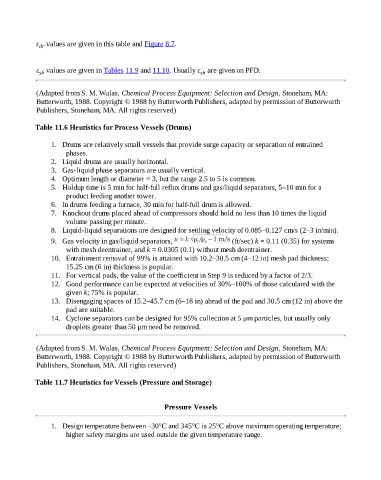
Table 11.6 Heuristics for Process Vessels (Drums)
1. Drums are relatively small vessels that provide surge capacity or separation of entrained
phases.
2. Liquid drums are usually horizontal.
3. Gas-liquid phase separators are usually vertical.
4. Optimum length or diameter = 3, but the range 2.5 to 5 is common.
5. Holdup time is 5 min for half-full reflux drums and gas/liquid separators, 5–10 min for a
product feeding another tower.
6. In drums feeding a furnace, 30 min for half-full drum is allowed.
7. Knockout drums placed ahead of compressors should hold no less than 10 times the liquid
volume passing per minute.
8. Liquid-liquid separations are designed for settling velocity of 0.085–0.127 cm/s (2–3 in/min).
9. Gas velocity in gas/liquid separators, (ft/sec) k = 0.11 (0.35) for systems
with mesh deentrainer, and k = 0.0305 (0.1) without mesh deentrainer.
10. Entrainment removal of 99% is attained with 10.2–30.5 cm (4–12 in) mesh pad thickness;
15.25 cm (6 in) thickness is popular.
11. For vertical pads, the value of the coefficient in Step 9 is reduced by a factor of 2/3.
12. Good performance can be expected at velocities of 30%–100% of those calculated with the
given k; 75% is popular.
13. Disengaging spaces of 15.2–45.7 cm (6–18 in) ahead of the pad and 30.5 cm (12 in) above the
pad are suitable.
14. Cyclone separators can be designed for 95% collection at 5 μm particles, but usually only
droplets greater than 50 μm need be removed.
(Adapted from S. M. Walas, Chemical Process Equipment: Selection and Design, Stoneham, MA:
Butterworth, 1988. Copyright © 1988 by Butterworth Publishers, adapted by permission of Butterworth
Publishers, Stoneham, MA. All rights reserved)
Table 11.7 Heuristics for Vessels (Pressure and Storage)
Pressure Vessels
1. Design temperature between –30°C and 345°C is 25°C above maximum operating temperature;
higher safety margins are used outside the given temperature range.