
Page 368 - Analysis, Synthesis and Design of Chemical Processes, Third Edition
P. 368
2. The design pressure is 10% or 0.69–1.7 bar (10–25 psi) over the max. operating pressure,
whichever is greater. The max. operating pressure, in turn, is taken as 1.7 bar (25 psi) above
the normal operation.
3. Design pressures of vessels operating at 0–0.69 bar (0–10 psig) and 95–540°C (200–1000°F)
are 2.76 barg (40 psig).
4. For vacuum operation, design pressures are 1 barg (15 psig) and full vacuum.
5. Minimum wall thickness for rigidity: 6.4 mm (0.25 in) for 1.07 m (42 in) dia. and less than 8.1
mm (0.32 in) for 1.07–1.52 m (42–60 in) dia., and 11.7 mm (0.38 in) for more than 1.52 m (60
in) dia.
6. Corrosion allowance 8.9 mm (0.35 in) for known corrosive conditions, 3.8 mm (0.15 in) for
noncorrosive streams, and 1.5 mm (0.06 in) for steam drums and air receivers.
7. Allowable working stresses are one-fourth of the ultimate strength of the material.
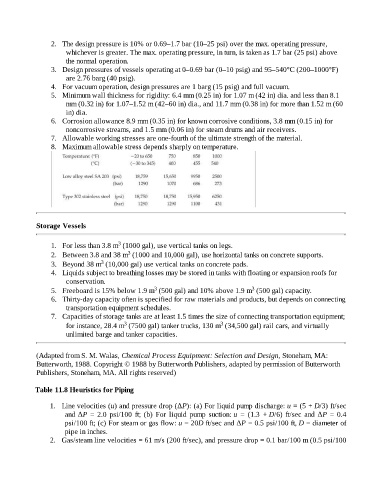
8. Maximum allowable stress depends sharply on temperature.
Storage Vessels
3
1. For less than 3.8 m (1000 gal), use vertical tanks on legs.
3
2. Between 3.8 and 38 m (1000 and 10,000 gal), use horizontal tanks on concrete supports.
3
3. Beyond 38 m (10,000 gal) use vertical tanks on concrete pads.
4. Liquids subject to breathing losses may be stored in tanks with floating or expansion roofs for
conservation.
3
3
5. Freeboard is 15% below 1.9 m (500 gal) and 10% above 1.9 m (500 gal) capacity.
6. Thirty-day capacity often is specified for raw materials and products, but depends on connecting
transportation equipment schedules.
7. Capacities of storage tanks are at least 1.5 times the size of connecting transportation equipment;
3
3
for instance, 28.4 m (7500 gal) tanker trucks, 130 m (34,500 gal) rail cars, and virtually
unlimited barge and tanker capacities.
(Adapted from S. M. Walas, Chemical Process Equipment: Selection and Design, Stoneham, MA:
Butterworth, 1988. Copyright © 1988 by Butterworth Publishers, adapted by permission of Butterworth
Publishers, Stoneham, MA. All rights reserved)
Table 11.8 Heuristics for Piping
1. Line velocities (u) and pressure drop (ΔP): (a) For liquid pump discharge: u = (5 + D/3) ft/sec
and ΔP = 2.0 psi/100 ft; (b) For liquid pump suction: u = (1.3 + D/6) ft/sec and ΔP = 0.4
psi/100 ft; (c) For steam or gas flow: u = 20D ft/sec and ΔP = 0.5 psi/100 ft, D = diameter of
pipe in inches.
2. Gas/steam line velocities = 61 m/s (200 ft/sec), and pressure drop = 0.1 bar/100 m (0.5 psi/100