
Page 62 - Analysis, Synthesis and Design of Chemical Processes, Third Edition
P. 62
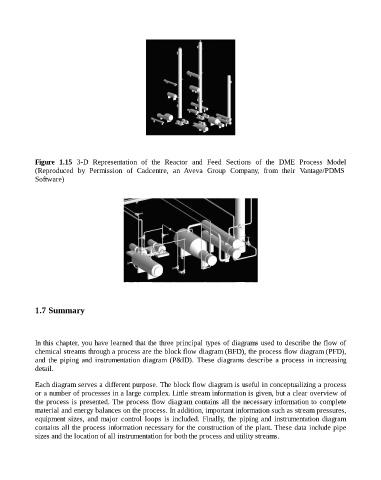
Figure  1.15  3-D  Representation  of  the  Reactor  and  Feed  Sections  of  the  DME  Process  Model
                    (Reproduced  by  Permission  of  Cadcentre,  an  Aveva  Group  Company,  from  their  Vantage/PDMS

                    Software)


                    1.7 Summary


                    In this chapter, you have learned that the three principal types of diagrams used to describe the flow of
                    chemical streams through a process are the block flow diagram (BFD), the process flow diagram (PFD),
                    and  the  piping  and  instrumentation  diagram  (P&ID).  These  diagrams  describe  a  process  in  increasing
                    detail.


                    Each diagram serves a different purpose. The block flow diagram is useful in conceptualizing a process
                    or a number of processes in a large complex. Little stream information is given, but a clear overview of
                    the process is presented. The process flow diagram contains all the necessary information to complete
                    material and energy balances on the process. In addition, important information such as stream pressures,
                    equipment  sizes,  and  major  control  loops  is  included.  Finally,  the  piping  and  instrumentation  diagram
                    contains all the process information necessary for the construction of the plant. These data include pipe

                    sizes and the location of all instrumentation for both the process and utility streams.