
Page 61 - Analysis, Synthesis and Design of Chemical Processes, Third Edition
P. 61
The best way to see how all the above elements fit together is to view the Virtual Plant Tour AVI file on
the CD that accompanies this text. The quality and level of detail that 3-D software is capable of giving
depend on the system used and the level of detailed engineering that is used to produce the model. Figures
1.13–1.15 were generated for the DME facility using the PDMS software package from Cadcentre, Inc.
(These figures and the Virtual_Plant_Tour.AVI file are presented here with permission of Cadcentre, Inc.)
In Figure 1.13, an isometric view of the DME facility is shown. All major process equipment, major
process and utility piping, and basic steel structures are shown. The pipe rack is shown running through
the center of the process, and steel platforms are shown where support of elevated process equipment is
required. The distillation sections are shown to the rear of the figure on the far side of the pipe rack. The
reactor and feed section is shown on the near side of the pipe rack. The elevation of the process
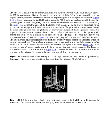
equipment is better illustrated in Figure 1.14, where the piping and structural steel have been removed.
The only elevated equipment apparent from this figure are the overhead condensers and reflux drums for
the distillation columns. The overhead condensers are located vertically above their respective reflux
drums to allow for the gravity flow of condensate from the exchangers to the drums. Figure 1.15 shows
the arrangement of process equipment and piping for the feed and reactor sections. The layout of
equipment corresponds to that shown in Figure 1.11. It should be noted that the control valve on the
discharge of the methanol feed pumps is located close to grade level for easy access.
Figure 1.13 Isometric View of Preliminary 3-D Plant Layout Model for DME Process (Reproduced by
Permission of Cadcentre, an Aveva Group Company, from their Vantage/ PDMS Software)
Figure 1.14 3-D Representation of Preliminary Equipment Layout for the DME Process (Reproduced by
Permission of Cadcentre, an Aveva Group Company, from their Vantage/ PDMS Software)