
Page 56 - Analysis, Synthesis and Design of Chemical Processes, Third Edition
P. 56
The minimum spacing between equipment should be set early on in the design. These distances are set for
safety purposes and should be set with both local and national codes in mind. A comprehensive list of the
recommended minimum distances between process equipment is given by Bausbacher and Hunt [5]. The
values for some basic process equipment are listed in Table 1.11.
Table 1.11 Recommended Minimum Spacing (in Feet) between Process Equipment for Refinery,
Chemical, and Petrochemical Plants
The sizing of process equipment should be completed and the approximate location on the plot plan
determined. Referring to Table B.1.3 for equipment specifications gives some idea of key equipment
sizes. For example, the data given for the reflux drums V-202 and V-203, reactor R-201, and towers T-
201 and T-202 are sufficient to sketch these units on the plot plan. However, pump sizes must be obtained
from vendors or previous jobs, and additional calculations for heat exchangers must be done to estimate
their required footprint on the plot plan. Calculations to illustrate the estimation of equipment footprints
are given in Example 1.11.
Example 1.11
Estimate the footprint for E-202 in the DME process.
From Table B.1.3 we have the following information:
Floating Head Shell-and-Tube design
Area = 171 m 2
Hot Side—Temperatures: in at 364°C and out at 281°C
Cold Side—Temperatures: in at 154°C and out at 250°C
Choose a two-shell pass and four-tube pass exchanger
Area per shell = 171/2 = 85.5 m 2
Using 12 ft, 1-inch OD tubes, 293 tubes per shell are needed
Assuming the tubes are laid out on a 1¼-inch square pitch, a 27-inch ID shell is required.
Assume that the front and rear heads (where the tube fluid turns at the end of the exchanger) are 30 inches
in diameter and require 2 feet each (including flanges), and that the two shells are stacked on top of each
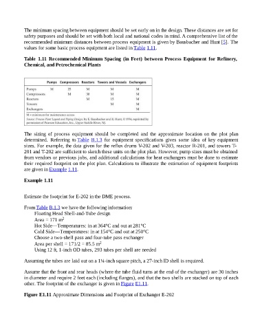
other. The footprint of the exchanger is given in Figure E1.11.
Figure E1.11 Approximate Dimensions and Footprint of Exchanger E-202