
Page 54 - Analysis, Synthesis and Design of Chemical Processes, Third Edition
P. 54
two-dimensional diagrams (PFD, P&ID, etc.). However, when it comes to the construction of the plant,
there are many issues that require a three-dimensional representation of the process. For example, the
location of shell and tube exchangers must allow for tube bundle removal for cleaning and repair.
Locations of pumps must allow for access for maintenance and replacement. For compressors, this access
may also require that a crane be able to remove and replace a damaged drive. Control valves must be
located at elevations that allow operator access. Sample ports and instrumentation must also be located
conveniently. For anyone who has toured a moderate-to-large chemical facility, the complexity of the
piping and equipment layout is immediately apparent. Even for experienced engineers, the review of
equipment and piping topology is far easier to accomplish in 3-D than 2-D. Due to the rapid increase in
computer power and advanced software, such representations are now done routinely using the computer.
In order to “build” an electronic representation of the plant in 3-D, all the information in the previously
mentioned diagrams must be accessed and synthesized. This in itself is a daunting task, and a complete
accounting of this process is well beyond the scope of this text. However, in order to give the reader a
flavor of what can now be accomplished using such software, a brief review of the principles of plant
layout design will be given. A more detailed account involving a virtual plant tour of the dimethyl ether
(DME) plant (Appendix B.1) is given on the CD accompanying this book.
For a complete, detailed analysis of the plant layout, all equipment sizes, piping sizes, PFDs, P&IDs, and
all other information should be known. However, for this description, a preliminary plant layout based on
information given in the PFD of Figure B.1.1 is considered. Using this figure and the accompanying
stream tables and equipment summary table (Tables B.1.1 and B.1.3), the following steps are followed.
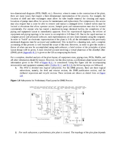
1. The PFD is divided into logical subsystems. For the DME process, there are three logical
subsections, namely, the feed and reactor section, the DME purification section, and the
methanol separation and recycle section. These sections are shown as dotted lines on Figure
1.8.
Figure 1.8 Subsystems for Preliminary Plan Layout for DME Process
2. For each subsystem, a preliminary plot plan is created. The topology of the plot plan depends