
Page 49 - Analysis, Synthesis and Design of Chemical Processes, Third Edition
P. 49
Indicators
Recorders
Controllers
Show Instrument Lines
For Utilities—Identify
Entrance Utilities
Exit Utilities
Exit to Waste Treatment Facilities
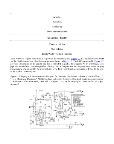
Each PFD will require many P&IDs to provide the necessary data. Figure 1.7 is a representative P&ID
for the distillation section of the benzene process shown in Figure 1.5. The P&ID presented in Figure 1.7
provides information on the piping, and this is included as part of the diagram. As an alternative, each
pipe can be numbered, and the specifics of every line can be provided in a separate table accompanying
this diagram. When possible, the physical size of the larger-sized unit operations is reflected by the size
of the symbol in the diagram.
Figure 1.7 Piping and Instrumentation Diagram for Benzene Distillation (adapted from Kauffman, D,
“Flow Sheets and Diagrams,” AIChE Modular Instruction, Series G: Design of Equipment, series editor
J. Beckman, AIChE, New York, 1986, vol 1, Chapter G.1.5, AIChE copyright © 1986 AIChE, all rights
reserved)