
Page 48 - Analysis, Synthesis and Design of Chemical Processes, Third Edition
P. 48
often contracted out.
The value of the PFD does not end with the construction of the plant. It remains the document that best
describes the process, and it is used in the training of operators and new engineers. It is consulted
regularly to diagnose operating problems that arise and to predict the effects of changes on the process.
1.3 Piping and Instrumentation Diagram (P&ID)
The piping and instrumentation diagram (P&ID), also known as mechanical flow diagram (MFD),
provides information needed by engineers to begin planning for the construction of the plant. The P&ID
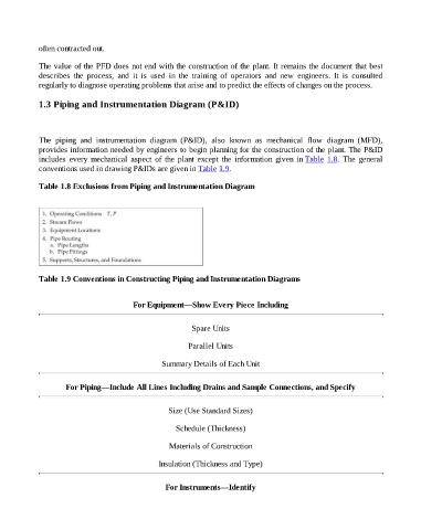
includes every mechanical aspect of the plant except the information given in Table 1.8. The general
conventions used in drawing P&IDs are given in Table 1.9.
Table 1.8 Exclusions from Piping and Instrumentation Diagram
Table 1.9 Conventions in Constructing Piping and Instrumentation Diagrams
For Equipment—Show Every Piece Including
Spare Units
Parallel Units
Summary Details of Each Unit
For Piping—Include All Lines Including Drains and Sample Connections, and Specify
Size (Use Standard Sizes)
Schedule (Thickness)
Materials of Construction
Insulation (Thickness and Type)
For Instruments—Identify