
Page 50 - Analysis, Synthesis and Design of Chemical Processes, Third Edition
P. 50
Utility connections are identified by a numbered box in the P&ID. The number within the box identifies
the specific utility. The key identifying the utility connections is shown in a table on the P&ID.
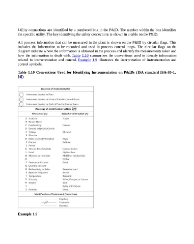
All process information that can be measured in the plant is shown on the P&ID by circular flags. This
includes the information to be recorded and used in process control loops. The circular flags on the
diagram indicate where the information is obtained in the process and identify the measurements taken and
how the information is dealt with. Table 1.10 summarizes the conventions used to identify information
related to instrumentation and control. Example 1.9 illustrates the interpretation of instrumentation and
control symbols.
Table 1.10 Conventions Used for Identifying Instrumentation on P&IDs (ISA standard ISA-S5-1,
[4])
Example 1.9