
Page 58 - Analysis, Synthesis and Design of Chemical Processes, Third Edition
P. 58
Therefore, the pipe diameter that satisfies both the heuristic and the continuity equation lies between 3 and
4 inches. Taking a conservative estimate, a 4-inch suction line is chosen for P-202.
The next step to consider is the placement of equipment within the plot plan. This placement must
be made considering the required access for maintenance of the equipment and also the initial
installation. Although this step may seem elementary, there are many cases [5] where the
incorrect placement of equipment subsequently led to considerable cost overruns and major
problems both during the construction of the plant and during maintenance operations. Consider
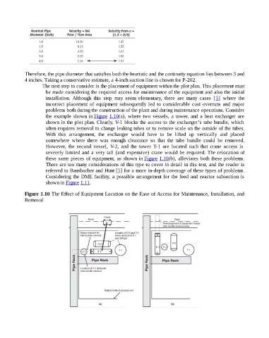
the example shown in Figure 1.10(a), where two vessels, a tower, and a heat exchanger are
shown in the plot plan. Clearly, V-1 blocks the access to the exchanger’s tube bundle, which
often requires removal to change leaking tubes or to remove scale on the outside of the tubes.
With this arrangement, the exchanger would have to be lifted up vertically and placed
somewhere where there was enough clearance so that the tube bundle could be removed.
However, the second vessel, V-2, and the tower T-1 are located such that crane access is
severely limited and a very tall (and expensive) crane would be required. The relocation of
these same pieces of equipment, as shown in Figure 1.10(b), alleviates both these problems.
There are too many considerations of this type to cover in detail in this text, and the reader is
referred to Bausbacher and Hunt [5] for a more in-depth coverage of these types of problems.
Considering the DME facility, a possible arrangement for the feed and reactor subsection is
shown in Figure 1.11.
Figure 1.10 The Effect of Equipment Location on the Ease of Access for Maintenance, Installation, and
Removal