
Page 60 - Analysis, Synthesis and Design of Chemical Processes, Third Edition
P. 60
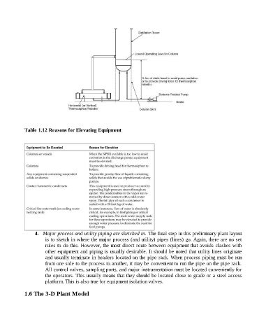
Table 1.12 Reasons for Elevating Equipment


                          4.   Major process and utility piping are sketched in. The final step in this preliminary plant layout
                                is to sketch in where the major process (and utility) pipes (lines) go. Again, there are no set
                                rules to do this. However, the most direct route between equipment that avoids clashes with
                                other equipment and piping is usually desirable. It should be noted that utility lines originate
                                and usually terminate in headers located on the pipe rack. When process piping must be run
                                from one side to the process to another, it may be convenient to run the pipe on the pipe rack.
                                All control valves, sampling ports, and major instrumentation must be located conveniently for
                                the operators. This usually means that they should be located close to grade or a steel access
                                platform. This is also true for equipment isolation valves.


                    1.6 The 3-D Plant Model