
Page 91 - Analysis, Synthesis and Design of Chemical Processes, Third Edition
P. 91
determining the separation and recycle structure of the process. For liquids, there are concerns about
azeotropes that complicate the separations scheme. For gases, there are concerns about whether high
pressures and/or low temperatures must be used to enable the desired separation to take place. In either
case gas compression is required, and, generally, this is an expensive operation. For example, the use of
membrane separators or pressure-swing adsorption requires that the gas be fed at an elevated pressure to
these units. If separation of a gas (vapor) is to be achieved using distillation, then a portion of the gas
must be condensed, which usually requires cooling the gas significantly below ambient temperatures. This
cooling process generally requires the use of compressors in the refrigeration cycle; the lower the desired
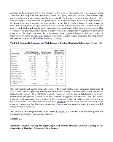
temperature, the more expensive the refrigeration. Some typical refrigerants and their range of
temperature are given in Table 2.2. Because separations of gases require expensive, low-temperature
refrigeration, they are avoided unless absolutely necessary.
Table 2.2 Common Refrigerants and Their Ranges of Cooling (Data from References [12] and [13])
Only refrigerants with critical temperatures above the typical cooling water condenser temperature of
45°C can be used in single-stage, noncascaded refrigeration systems. Therefore, such systems are usually
limited to the range of –45 to –60°C (for example, propylene, propane, and methyl chloride). For lower
temperatures, refrigeration systems with two different refrigerants are required, with the lower-
temperature refrigerant rejecting heat to the higher-temperature refrigerant, which in turn rejects heat to
the cooling water. Costs of refrigeration are given in Chapter 8, and these costs increase drastically as the
temperature decreases. For this reason, separations of gases requiring very low temperatures are avoided
unless absolutely necessary.
As a review of the concepts covered in this chapter, Example 2.6 is presented to illustrate the approach to
formulating a preliminary process flow diagram.
Example 2.6
Illustrative Example Showing the Input/Output and Recycle Structure Decisions Leading to the
Generation of Flowsheet Alternatives for a Process