
Page 343 - Applied Process Design For Chemical And Petrochemical Plants Volume III
P. 343
66131_Ludwig_CH11A 5/30/2001 4:49 PM Page 301
Refrigeration Systems 301
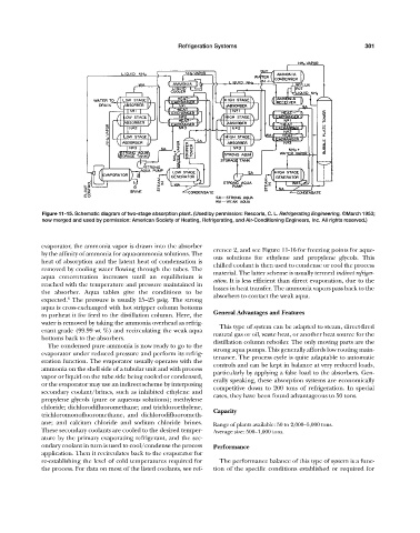
Figure 11-15. Schematic diagram of two-stage absorption plant. (Used by permission: Rescorla, C. L. Refrigerating Engineering, ©March 1953;
now merged and used by permission: American Society of Heating, Refrigerating, and Air-Conditioning Engineers, Inc. All rights reserved.)
evaporator, the ammonia vapor is drawn into the absorber
erence 2, and see Figure 11-16 for freezing points for aque-
by the affinity of ammonia for aqua-ammonia solutions. The
ous solutions for ethylene and propylene glycols. This
heat of absorption and the latent heat of condensation is
chilled coolant is then used to condense or cool the process
removed by cooling water flowing through the tubes. The
material. The latter scheme is usually termed indirect refriger-
aqua concentration increases until an equilibrium is
ation. It is less efficient than direct evaporation, due to the
reached with the temperature and pressure maintained in
losses in heat transfer. The ammonia vapors pass back to the
the absorber. Aqua tables give the conditions to be absorbers to contact the weak aqua.
6
expected. The pressure is usually 15—25 psig. The strong
aqua is cross-exchanged with hot stripper column bottoms
General Advantages and Features
to preheat it for feed to the distillation column. Here, the
water is removed by taking the ammonia overhead as refrig-
This type of system can be adapted to steam, direct-fired
erant grade (99.99 wt %) and recirculating the weak aqua
natural gas or oil, waste heat, or another heat source for the
bottoms back to the absorbers.
distillation column reboiler. The only moving parts are the
The condensed pure ammonia is now ready to go to the
strong aqua pumps. This generally affords low routing main-
evaporator under reduced pressure and perform its refrig-
tenance. The process cycle is quite adaptable to automatic
eration function. The evaporator usually operates with the
controls and can be kept in balance at very reduced loads,
ammonia on the shell side of a tubular unit and with process
particularly by applying a false load to the absorbers. Gen-
vapor or liquid on the tube side being cooled or condensed,
erally speaking, these absorption systems are economically
or the evaporator may use an indirect scheme by interposing
competitive down to 200 tons of refrigeration. In special
secondary coolant/brines, such as inhibited ethylene and
cases, they have been found advantageous to 50 tons.
propylene glycols (pure or aqueous solutions); methylene
chloride; dichlorodifluoromethane; and trichloroethylene,
Capacity
trichloromonofluoromethane, and dichlorodifluorometh-
ane; and calcium chloride and sodium chloride brines. Range of plants available: 50 to 2,000—5,000 tons.
These secondary coolants are cooled to the desired temper- Average size: 500—1,000 tons.
ature by the primary evaporating refrigerant, and the sec-
ondary coolant in turn is used to cool/condense the process Performance
application. Then it recirculates back to the evaporator for
re-establishing the level of cold temperatures required for The performance balance of this type of system is a func-
the process. For data on most of the listed coolants, see ref- tion of the specific conditions established or required for