
Page 344 - Applied Process Design For Chemical And Petrochemical Plants Volume III
P. 344
66131_Ludwig_CH11A 5/30/2001 4:49 PM Page 302
302 Applied Process Design for Chemical and Petrochemical Plants
Table 11-1
Representative Single-Stage Absorption Plant
Operating Conditions
(1) (2)* (3)*
Tons Refrigeration 500 650 800
o
Temperature, F
Brine to evaporator (or cooler) . . . a 16
Brine from evaporator . . . a 20
Evaporator 14.8 29 30.8
Weak aqua to absorbers 112 126 102
Strong aqua from absorbers 89.6 104 90
Water to absorbers 87.8 86.7 70
Water from absorbers 99 94.1 79
Strong aqua from heat exchangers 224.5 178 248
Weak aqua to heat exchangers 271 210 283
Liquid ammonia from condenser 85.1 93 92
Water to condenser 77 81 79
Water from condenser 87.8 86.7 87.3
Steam in generator 272 b 222 298
Pressure, Psig
Evaporator 6 43.8 2.3 in. Hg.
Absorbers 6 43.8 2.3 in. Hg.
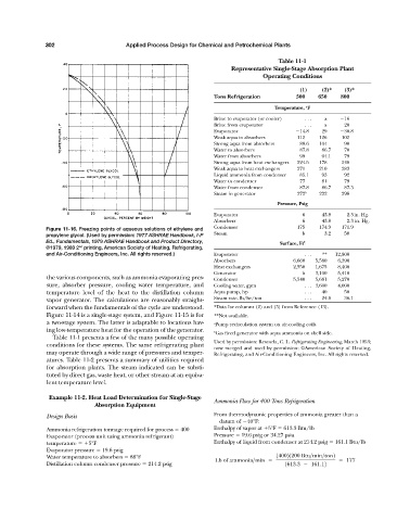
Figure 11-16. Freezing points of aqueous solutions of ethylene and Condenser 175 174.9 171.9
propylene glycol. (Used by permission: 1977 ASHRAE Handbook, I-P Steam b 3.2 50
Ed., Fundamentals, 1979 ASHRAE Handbook and Product Directory, Surface, Ft 2
©1979, 1980 2 printing, American Society of Heating, Refrigerating,
nd
and Air-Conditioning Engineers, Inc. All rights reserved.) Evaporator . . . ** 12,800
Absorbers 6,660 5,580 6,390
Heat exchangers 2,550 1,675 8,400
Generator b 3,100 5,410
the various components, such as ammonia evaporating pres- Condenser 5,540 5,661 5,270
sure, absorber pressure, cooling water temperature, and Cooling water, gpm . . . 3,600 4,000
temperature level of the heat to the distillation column Aqua pump, hp . . . 40 50
vapor generator. The calculations are reasonably straight- Steam rate, lb/hr/ton . . . 24.6 36.1
forward when the fundamentals of the cycle are understood. *Data for columns (2) and (3) from Reference (13).
Figure 11-14 is a single-stage system, and Figure 11-15 is for **Not available.
a two-stage system. The latter is adaptable to locations hav- a Pump recirculation system on air-cooling coils.
ing low-temperature heat for the operation of the generator. b Gas fired generator with aqua ammonia on shell side.
Table 11-1 presents a few of the many possible operating
Used by permission: Rescorla, C. L. Refrigerating Engineering, March 1953;
conditions for these systems. The same refrigerating plant
now merged and used by permission: ©American Society of Heating,
may operate through a wide range of pressures and temper- Refrigerating, and Air-Conditioning Engineers, Inc. All rights reserved.
atures. Table 11-2 presents a summary of utilities required
for absorption plants. The steam indicated can be substi-
tuted by direct gas, waste heat, or other stream at an equiva-
lent temperature level.
Example 11-2. Heat Load Determination for Single-Stage
Ammonia Flow for 400 Tons Refrigeration
Absorption Equipment
Design Basis From thermodynamic properties of ammonia greater than a
datum of 40°F:
Ammonia refrigeration tonnage required for process 400 Enthalpy of vapor at 5°F 613.3 Btu/lb
Evaporator (process unit using ammonia refrigerant) Pressure 19.6 psig or 34.27 psia
temperature 5°F Enthalpy of liquid from condenser at 214.2 psig 161.1 Btu/lb
Evaporator pressure 19.6 psig
Water temperature to absorbers 88°F 140021200 Btu>min>ton2
Lb of ammonia>min 177
Distillation column condenser pressure 214.2 psig 1613.3 161.12