Page 412 - Applied Process Design For Chemical And Petrochemical Plants Volume III
P. 412

66131_Ludwig_CH12A  6/1/01 11:00 AM  Page 369


                                                   Compression Equipment (Including Fans)                             369

                                                                                           Table 12-1
                                                                             General Compression and Vacuum Limits
                                                                                       Approx. Max.  Approx. Max.  Approx. Max.
                                                                                       Commercially  Compression  Compression
                                                                                        Used Disch.   Ratio per   Ratio per Case
                                                                      Compressor Type   Press., psia  Stage    or Machine
                                                                      Reciprocating    35,000—50,000  10       as required
                                                                      Centrifugal      03,000—05,000  3—4.5      8—10
                                                                      Rotary displacement  0,0100—0,0130  4       4
                                                                      Axial flow       0,0080—0,0130  1.2—1.5    5—6.5

                                                                      Vacuum Pump Type             Approx. Suction Pressure
                                                                                                    Attainable, mm Hg abs
                                                                      Centrifugal                          6
                                                                      Reciprocating                        0.3
                                                                      Steam jet ejector                   00.05
                                                                      Rotary displacement                 10  5
                                                                      Oil diffusion                 10  7  (or 10  4  micron)
                                                                      Mercury or oil diffusion plus rotary  less than 10  7
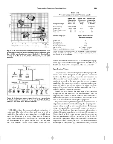
                 Figure 12-1C. Typical application ranges for turbocompressor capa-
                                                                      Used by permission and compiled in part from: Dobrowolski, Z. Chemical Engineering,
                 bilities extend over wide ranges of volume flow and pressures. Note:  V. 63, p. 181, ©1956 and Des Jardins, P. R. Chemical Engineering, V. 63, p. 178, ©1956.
                 Bar.   14.50   psi. (Used by permission: Nissler, K. H. Chemical Engi-  McGraw-Hill, Inc. All rights reserved.
                 neering,  V. 98, No. 3, p. 104, ©1991. McGraw-Hill, Inc. All rights
                 reserved.)
                                                                      nature of the fluid, are all involved in identifying the equip-
                                                                      ment type best suited for the application. See Monroe, 40
                                                                           34
                                                                                      43
                                                                      Huff, and Patton for comparison. Also see Leonard. 71
                                                                      Specification Guides

                                                                        Compressor cylinders or other pressure-developing mech-
                                                                      anisms are never designed by the process companies
                                                                      involved in their operation, except in rare instances in
                                                                      which special know-how is available or secret process infor-
                                                                      mation is involved. In the latter case, the process company
                                                                      might have the compressor cylinders (or compression com-
                                                                      ponents) built in accordance with special plans, purchase
                                                                      standard frames or housings, and then assemble the driver,
                                                                      cylinder, and packing at the plant site.
                                                                        Usually the selection of the basic type of compression
                                                                      equipment for the operation can be determined prior to
                                                                      inquiring of the manufacturers. However, when in doubt or
                                                                      where multiple types may be considered, inquiries should be
                 Figure 12-1D. Basic compressor types. (Used by permission: Coker,
                 A. K. Hydrocarbon Processing, V. 73, No. 7, p. 39, ©1994. Gulf Pub-  sent to all manufacturers offering the equipment.
                 lishing Co., Houston, Texas. All rights reserved.)     Preparation of complete and appropriate specifications is
                                                                      of paramount importance in obtaining the proper perfor-
                                                                      mance rating as well as price considerations. Preliminary
                                                                      design rating calculations are usually prepared as guides or
                  Table 12-1 outlines the compression limits for this type of  checks. The final and firm performance information is
                equipment. The value of the chart and table is to aid in  obtained from the manufacturer of the specific equipment.
                establishing the probable types of equipment suitable for an  No standards of design exist among manufacturers; there-
                operation. However, as in many other process situations,  fore, the performance will vary according to the details of
                equipment is designed to handle special cases that might  the specific equipment. All performance will be close to the
                not be indicated by the guide. Usually inlet cfm, tempera-  requirement, but none may be exact. This is the point where
                ture, and pressure, as well as the outlet conditions and  knowledge of compressor types and details is important to
   407   408   409   410   411   412   413   414   415   416   417