
Page 407 - Applied Process Design For Chemical And Petrochemical Plants Volume III
P. 407
66131_Ludwig_CH11A 5/30/2001 4:51 PM Page 364
364 Applied Process Design for Chemical and Petrochemical Plants
Table 11-14
Theoretical Compressor Power for a Refrigerant-12
Plant Requiring 10 Tons at 44°F, 30 Tons at 34°F,
and 20 Tons at 24°F
% Reduction
Type of System Hp from Max.
One Compressor:
All evaporators at same temp. (24°F) 52.7 0
**Individual exp. valves and
back-pressure valves 52.7 0
Multiple exp. valves and
back-pressure valves 52.7 0
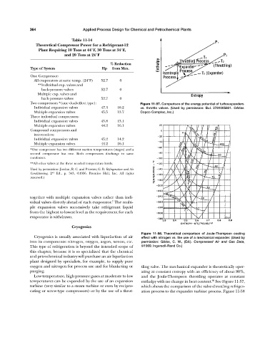
Two compressors *(one dual-effect type): Figure 11-57. Comparison of the energy potential of turboexpanders
Individual expansion valves 47.3 10.2 vs. throttle valves. (Used by permission: Bul. 2781005601. ©Atlas
Multiple expansion valves 45.5 13.7 Copco Comptec, Inc.)
Three individual compressors:
Individual expansion valves 45.8 13.1
Multiple expansion valves 44.2 16.1
Compound compressors and
intercoolers:
Individual expansion valves 45.2 14.2
Multiple expansion valves 44.2 16.1
*One compressor has two different suction temperatures (stages) and a
second compressor has one. Both compressors discharge to same
condenser.
**All other valves at the three needed temperature levels.
Used by permission: Jordan, R. C. and Priester, G. B. Refrigeration and Air
Conditioning, 2 nd Ed., p. 343, ©1956. Prentice Hall, Inc. All rights
reserved.)
together with multiple expansion valves rather than indi-
7
vidual valves directly ahead of each evaporator. The multi-
ple expansion valves successively take refrigerant liquid
from the highest to lowest level as the requirement for each
evaporator is withdrawn.
Cryogenics
Figure 11-58. Theoretical comparison of Joule-Thompson cooling
Cryogenics is usually associated with liquefaction of air effect with nitrogen vs. the use of a mechanical expander. (Used by
into its components: nitrogen, oxygen, argon, xenon, etc. permission: Gibbs, C. W., (Ed.). Compressed Air and Gas Data,
This type of refrigeration is beyond the intended scope of ©1969. Ingersoll-Rand Co.)
this chapter, because it is so specialized that the chemical
and petrochemical industry will purchase an air liquefaction
plant designed by specialists, for example, to supply pure
oxygen and nitrogen for process use and for blanketing or tling valve. The mechanical expander is theoretically oper-
purging. ating at constant entropy with an efficiency of about 80%,
Low-temperature, high-pressure gases at moderate to low and the Joule-Thompson throttling operates at constant
60
temperatures can be expanded by the use of an expansion enthalpy with no change in heat content. See Figure 11-57,
turbine (very similar to a steam turbine or even by recipro- which shows the comparison of the valve-throttling refriger-
cating or screw-type compressors) or by the use of a throt- ation process to the expander turbine process. Figure 11-58