Page 408 - Applied Process Design For Chemical And Petrochemical Plants Volume III
P. 408

66131_Ludwig_CH11A  5/30/2001 4:51 PM  Page 365


                                                                Refrigeration Systems                                      365


                        (A)


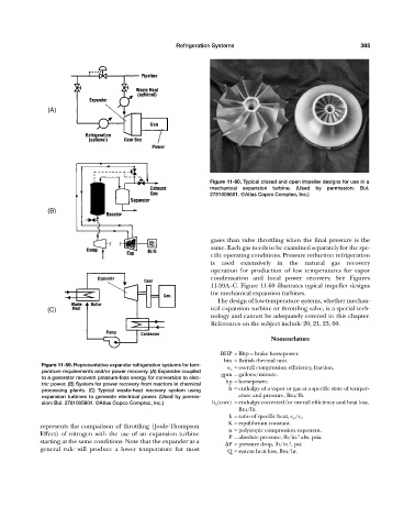
                                                                           Figure 11-60. Typical closed and open impeller designs for use in a
                                                                           mechanical expansion turbine. (Used by permission: Bul.
                                                                           2781005601. ©Atlas Copco Comptec, Inc.)

                        (B)


                                                                           gases than valve throttling when the final pressure is the
                                                                           same. Each gas needs to be examined separately for the spe-
                                                                           cific operating conditions. Pressure reduction refrigeration
                                                                           is used extensively in the natural gas recovery
                                                                           operation for production of low temperatures for vapor
                                                                           condensation and local power recovery. See Figures
                                                                           11-59A—C. Figure 11-60 illustrates typical impeller designs
                                                                           for mechanical expansion turbines.
                                                                             The design of low-temperature systems, whether mechan-
                       (C)                                                 ical expansion turbine or throttling valve, is a special tech-
                                                                           nology and cannot be adequately covered in this chapter.
                                                                           References on the subject include 20, 21, 23, 60.

                                                                                              Nomenclature

                                                                              BHP = Bhp = brake horsepower.
                                                                               btu = British thermal unit.
                      Figure 11-59. Representative expander refrigeration systems for tem-  e o = overall compression efficiency, fraction.
                      perature requirements and/or power recovery. (A) Expander coupled  gpm = gallons/minute.
                      to a generator recovers pressure-loss energy for conversion to elec-
                      tric power. (B) System for power recovery from reactors in chemical  hp = horsepower.
                      processing plants. (C) Typical waste-heat recovery system using  h = enthalpy of a vapor or gas at a specific state of temper-
                      expansion turbines to generate electrical power. (Used by permis-  ature and pressure, Btu/lb.
                      sion: Bul. 2781005601. ©Atlas Copco Comptec, Inc.)    h 2 (corr) = enthalpy corrected for overall efficiency and heat loss,
                                                                                    Btu/lb.
                                                                                 k = ratio of specific heat, c p /c v .
                                                                                 K = equilibrium constant.
                     represents the comparison of throttling (Joule-Thompson
                                                                                 n = polytropic compression exponent.
                     Effect) of nitrogen with the use of an expansion turbine
                                                                                                       2
                                                                                 P = absolute pressure, lb/in. abs, psia.
                     starting at the same conditions. Note that the expander as a                   2
                                                                                 P = pressure drop, lb/in. , psi.
                     general rule will produce a lower temperature for most      Q = system heat loss, Btu/hr.
   403   404   405   406   407   408   409   410   411   412   413