
Page 404 - Applied Process Design For Chemical And Petrochemical Plants Volume III
P. 404
66131_Ludwig_CH11A 5/30/2001 4:50 PM Page 361
Refrigeration Systems 361
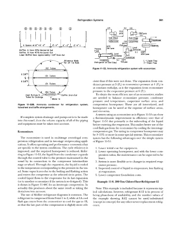
Figure 11-53. Ammonia refrigeration system with economizer.
cient than if this were not done. The expansion from con-
denser pressure at 3 (P 2 ) to economizer pressure at 4 (P 3 ) is
at constant enthalpy, as is the expansion from economizer
pressure to the evaporator pressure at 6 (P 1 ).
To obtain the most efficient use of an economizer, studies
are needed to balance economizer pressure, condenser
pressure and temperature, evaporator surface area, and
Figure 11-52B. Ammonia condenser for refrigeration system; compression horsepower. These are all interrelated, and
tubesheet and baffle arrangements. horsepower can be saved at the expense of surface areas,
and vice-versa.
A system using an economizer as in Figure 11-53 can show
If complete system drainage and pump-out is to be made a thermodynamic improvement in efficiency over that of
into this vessel, then the volume capacity of all of the piping Figure 11-51 due primarily to the subcooling of the liquid
and equipment must be taken into account. before entering the evaporator. This makes better use of the
cool flash gas from the economizer by cooling the interstage
Economizers compression gas. The saving in compressor horsepower may
be 3—15% or more in some special systems. This economizer
The economizer is used in multistage centrifugal com- system has the following advantages over the simple system
pression refrigeration and in two-stage reciprocating appli- of Figure 11-51:
cations. It offers operating and performance economics that
are specific to the system conditions. The cycle efficiency is 1. Lower initial cost for equipment.
improved, and the required horsepower is reduced. Refer- 2. Lower operating horsepower, and with the lower com-
ring to Figure 11-53, the liquid from the condenser expands pression ratios, the maintenance can be expected to be
through the control valve to the pressure maintained in the lower.
vessel by its connection to the compressor intermediate 3. System is more flexible as to changes in required evap-
stage or wheel. Through the expansion, the liquid is cooled orator pressure.
to the temperature corresponding to the pressure in the ves- 4. Improved control of liquid to evaporators, less flashing
sel. Some vapor leaves due to the boiling and flashing action at evaporators.
and enters the compressor at the selected tie-in point. The 5. Lower compressor foundation costs.
cooled liquid flows to the evaporator for its last expansion
(or to another economizer if the system is so designed). This Example 11-8. 200-Ton Chloro-Fluor-Refrigerant-12
is shown in Figure 11-48C for an isentropic compression. In
actuality this produces about the same result as taking the Note: This example is included because it represents typ-
deviations into account. ical calculations; however, refrigerant R-12 is in process of
The use of Mollier refrigerant diagrams is common. The being phased-out of availability, and the number values of
refrigerant is compressed from Point 1 to 2, while at 1A cool the example showing R-12 cannot be used/substituted
flash gas enters from the economizer to cool the gas to 1B, (except in concept) for any other newer replacement refrig-
so that the last part of the compression is slightly more effi- erant.