
Page 406 - Applied Process Design For Chemical And Petrochemical Plants Volume III
P. 406
66131_Ludwig_CH11A 5/30/2001 4:51 PM Page 363
Refrigeration Systems 363
Figure 11-55A. Refrigerating system with propane refrigerant. (Used
by permission: Charls, J., Jr. Tech Paper RP 468, ©1950. Dresser-
Rand Company.)
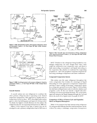
Figure 11-56. Cascade type low-temperature refinery refrigeration
cycle. (Used by permission: Charls, J., Jr. Tech Paper RP-468, ©1950.
Dresser-Rand Company.
4
160°F. Ethylene is the refrigerant being handled in cen-
trifugal compressors (in some designs these three units
might be combined in one compressor case), and there is
flash intercooling (economizer) and liquid subcooling to
the evaporator. The ethylene is condensed by evaporating
propylene at 50°F. The propylene comprises a separate sys-
tem using centrifugal compressors and water condensers.
Compound Compression System
This system uses the same refrigerant throughout the
Figure 11-55B. Centrifugal system with propane refrigerant. (Used by entire compression but includes the advantages of liquid
permission: Charls, J., Jr. Tech Paper RP-468, © 1950. Dresser-Rand subcooling for close approach to evaporator temperature
Company.) and direct vapor cooling of interstage compression vapors
by a refrigerant operated intercooler. Figure 11-56 includes
the shell and coil liquid intercooler in both the ethylene and
Cascade Systems propylene cycles. It does not include a liquid subcooler-
exchanger for suction gas desuperheating. The temperature
A cascade system uses one refrigerant to condense the approach between the liquid passing through the coil and
other primary refrigerant that is operating at the desired that in the shell of the liquid cooler is usually 10—20°F. 1
evaporator temperature. This approach is usually used for
temperature levels less than 80°F, when light hydrocarbon Comparison of Effect of System Cycle and Expansion
gases or other low boiling gases and vapors are being cooled. Valves on Required Horsepower
To obtain the highest overall efficiency for the system, the
refrigerants for the two superimposed systems are different. Table 11-14 compares four basic systems using refrigerant
Figure 11-56 is typical of the type of system that can be 12, and generally indicates that the total horsepower can be
arranged to suit a primary refrigeration load of 600 tons at reduced by using a multistage compression arrangement