
Page 402 - Applied Process Design For Chemical And Petrochemical Plants Volume III
P. 402
66131_Ludwig_CH11A 5/30/2001 4:50 PM Page 359
Refrigeration Systems 359
Enthalpy of saturated vapor at 105°F 633.4 Btu/lb.
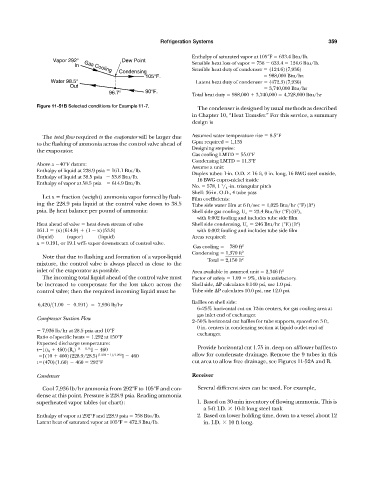
Vapor 292° Dew Point
In Gas Cooling Sensible heat loss of vapor 758 633.4 124.6 Btu/lb.
Sensible heat duty of condenser (124.6)(7,936)
Condensing
105°F. 988,000 Btu/hr.
Water 98.5° Latent heat duty of condenser (472.3)(7,936)
Out 3,740,000 Btu/hr
96.7° 90°F. Total heat duty 988,000 3,740,000 4,728,000 Btu/hr
Figure 11-51B Selected conditions for Example 11-7.
The condenser is designed by usual methods as described
in Chapter 10, “Heat Transfer.” For this service, a summary
design is
The total flow required to the evaporator will be larger due Assumed water temperature rise 8.5°F
to the flashing of ammonia across the control valve ahead of Gpm required 1,135
Designing stepwise:
the evaporator.
Gas cooling LMTD 55.0°F
Condensing LMTD 11.3°F
Above a 40°F datum:
Assume a unit:
Enthalpy of liquid at 228.9 psia 161.1 Btu/lb.
Duplex tubes: 1-in. O.D. 16 ft, 0 in. long, 16 BWG steel outside,
Enthalpy of liquid at 38.5 psia 53.8 Btu/lb.
16 BWG cupro-nickel inside
Enthalpy of vapor at 58.5 psia 614.9 Btu/lb.
1
No. 578, 1 / 4 -in. triangular pitch
Shell: 36-in. O.D., 4 tube pass
Let x fraction (weight) ammonia vapor formed by flash- Film coefficients:
ing the 228.9 psia liquid at the control valve down to 38.5 Tube side water film at 6 ft/sec 1,025 Btu/hr (°F)(ft )
2
psia. By heat balance per pound of ammonia: Shell side gas cooling, U o 23.4 Btu/hr (°F)(ft ),
2
with 0.002 fouling and includes tube side film
2
Heat ahead of valve heat down stream of valve Shell side condensing, U o 246 Btu/hr (°F.)(ft )
161.1 (x)(614.9) (1 x)(53.8) with 0.002 fouling and includes tube side film
(liquid) (vapor) (liquid) Areas required:
x 0.191, or 19.1 wt% vapor downstream of control valve.
Gas cooling 0780 ft 2
Condensing 1,370 ft 2
Note that due to flashing and formation of a vapor-liquid
Total 2,150 ft 2
mixture, the control valve is always placed as close to the
inlet of the evaporator as possible. Area available in assumed unit 2,346 ft 2
The incoming total liquid ahead of the control valve must Factor of safety 1.09 9%, this is satisfactory.
be increased to compensate for the loss taken across the Shell side, P calculates 0.140 psi, use 1.0 psi.
control valve; then the required incoming liquid must be Tube side P calculates 10.0 psi, use 12.0 psi.
Baffles on shell side:
6,420>11.00 0.1912 7,936 lb>hr
6—25% horizontal cut on 12-in centers, for gas cooling area at
gas inlet end of exchanger.
Compressor Suction Flow
2—50% horizontal cut baffles for tube supports, spaced on 3 ft,
0 in. centers in condensing section at liquid outlet end of
7,936 lb/hr at 28.5 psia and 10°F
exchanger.
Ratio of specific heats 1.292 at 150°F
Expected discharge temperature:
t [(t 8 460)(R c ) (k 1)/k ] 460 Provide horizontal cut 1.75 in. deep on all lower baffles to
t [(10 460)(228.9/28.5) (1.292 1)/1.292 ] 460 allow for condensate drainage. Remove the 9 tubes in this
t (470)(1.60) 460 292°F cut area to allow free drainage, see Figures 11-52A and B.
Condenser Receiver
Cool 7,936 lb/hr ammonia from 292°F to 105°F and con- Several different sizes can be used. For example,
dense at this point. Pressure is 228.9 psia. Reading ammonia
superheated vapor tables (or chart): 1. Based on 30-min inventory of flowing ammonia. This is
a 5-ft I.D. 10-ft long steel tank
Enthalpy of vapor at 292°F and 228.9 psia 758 Btu/lb. 2. Based on lower holding time, down to a vessel about 12
Latent heat of saturated vapor at 105°F 472.3 Btu/lb. in. I.D. 10 ft long.