
Page 405 - Applied Process Design For Chemical And Petrochemical Plants Volume III
P. 405
66131_Ludwig_CH11A 5/30/2001 4:50 PM Page 362
362 Applied Process Design for Chemical and Petrochemical Plants
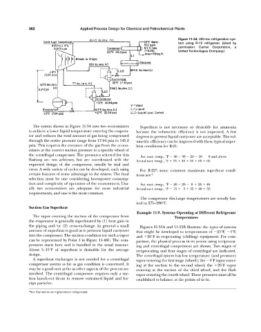
Figure 11-54. 200-ton refrigeration sys-
tem using R-12 refrigerant. (Used by
permission: Carrier Corporation, a
United Technologies Company.)
The system shown in Figure 11-54 uses two economizers Superheat is not necessary or desirable for ammonia
to achieve a lower liquid temperature entering the evapora- because the volumetric efficiency is not improved. A few
tor and reduces the total amount of gas being compressed degrees to prevent liquid carry-over are acceptable. The vol-
through the entire pressure range from 17.94 psia to 145.2 umetric efficiency can be improved with these typical super-
psia. This requires the entrance of the gas from the econo- heat conditions for R-21:
mizers at the correct suction pressure to a specific wheel of
the centrifugal compressor. The pressures selected for this
Sat. suct. temp., °F 40 30 20 10 0 and above
flashing are not arbitrary, but are coordinated with the Actual suct. temp., °F 35 45 55 65 65
expected design of the compressor, usually by trial and
error. A wide variety of cycles can be developed, each using For R-22*, some common maximum superheat condi-
certain features of some advantage to the system. The final tions are: 3
selection must be one considering horsepower consump-
tion and complexity of operation of the economizers. Usu- Sat. suct. temp., °F 40 20 0 20 40
ally two economizers are adequate for most industrial Actual suct. temp., °F 15 5 25 40 55
requirements, and one is the most common.
The compressor discharge temperatures are usually lim-
ited to 275—290°F.
Suction Gas Superheat
Example 11-9. Systems Operating at Different Refrigerant
The vapor entering the suction of the compressor from Temperatures
the evaporator is generally superheated by (1) heat gain in
the piping and/or (2) cross-exchange. In general a small Figures 11-55A and 11-55B illustrate the types of systems
amount of superheat is good as it prevents liquid carryover that might be developed to temperatures of 25°F, 4°F,
into the compressor. The suction condition for such a vapor and 26°F in evaporating (chilling) equipment. For com-
can be represented by Point 1 in Figure 11-48C. The com- parison, the physical process tie-in points using reciprocat-
pression starts here and is handled in the usual manner. ing and centrifugal compressors are shown. Two stages of
About 5—15°F of superheat is desirable for the average reciprocating and four stages of centrifugal are indicated.
design. The centrifugal system has low temperature (and pressure)
A superheat exchanger is not needed for a centrifugal vapor entering the first stage (wheel); the 4°F vapor enter-
compressor system as far as gas condition is concerned. It ing at the suction to the second wheel; the 26°F vapor
may be a good unit as far as other aspects of the process are entering at the suction of the third wheel; and the flash
involved. The centrifugal compressor requires only a suc- vapor entering the fourth wheel. These pressures must all be
tion knock-out drum to remove entrained liquid and for- established to balance at the points of tie-in.
eign particles.
*See discussion on replacement refrigerants.