
Page 401 - Applied Process Design For Chemical And Petrochemical Plants Volume III
P. 401
66131_Ludwig_CH11A 5/30/2001 4:50 PM Page 358
358 Applied Process Design for Chemical and Petrochemical Plants
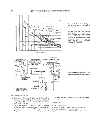
Figure 11-50. Comparison of refriger-
ants at condensing temperatures of
85°F and 105°F.
Note: Bhp values based on 75% overall
efficiency. This is not exact, as effi-
ciency changes with specific system
conditions. (Plotted from data of
Boteler, H. W. Natural Gasoline Supply
Men’s Engr. Data Book, 7 Ed., p. 40,
th
©1957; and Huff, R. L. Petroleum
Refiner, p. 111, Feb. 1959.)
Figure 11-51. Example problem: 300-ton
ammonia refrigeration system, Example
11-7.
(Text continued from page 353)
be made smaller, if possible, to conserve compressor
2. Evaporator, refrigerant side: 23.8 psig (38.5 psia). This
horsepower.
corresponds to a boiling or evaporating refrigerant
temperature of the required 10°F. See Reference 1 or
Ammonia Flow
other ammonia tables.
3. Compressor suction: 13.8 psig (28.5 psia). This allows Heat duty 3,600,000 Btu/hr.
an assumed (must be checked) pressure of 10 psi in the Tonnage 3,600,000/12,000 Btu/ton ref. 300 tons ref.
piping from the evaporator to the compressor suction Latent heat ammonia at 10°F 561.1 Btu/lb.
flange. This should be a conservative drop and should Liquid ammonia vaporized 3,600,000/561.1 6,420 lb/hr.