Page 46 - Applied Process Design For Chemical And Petrochemical Plants Volume III
P. 46

66131_Ludwig_CH10B  5/30/2001 4:17 PM  Page 36


                       36                        Applied Process Design for Chemical and Petrochemical Plants

                         Errors in tube count can cause recalculation in expected  Figures 10-25A—E are for U-bundle tubes and require a
                       exchanger performances. 125                           wide blank space across the center of the tubesheet to rec-
                                                                             ognize the U-bend requirement at the far end of the tube
                       Number of tubes>shell:                                bundle, see Figures 10-1E, 10-1A item U, and 10-1K. Figures
                       112 Triangular pitch                                  10-25F—K are for fixed tubesheet layouts.
                                    2
                            31D s   K 1 2  >4   K 2 4   p 1D s   K 1 23K 3 1n2   K 4 4  Before fabrication, an exact layout of the tubes, clear-
                       N t
                                           1.2231p2 2                        ances, etc., must be made; however, for most design pur-
                                                                     (10-2)  poses, the tube counts for fixed tubesheets and floating
                                                                             heads as given in Tables 10-9 and 10-10 are quite accurate. A
                       122 Square pitch
                                    2
                            31D s   K 1 2  >4   K 2 4   p 1D s   K 1 23K 3 1n2   K 4 4  comparison with tube counts in other references (19, 70)
                       N t                                                   indicates an agreement of   3% in the small diameters up
                                             1p2 2                                      1
                                                                             to about 23  / 4 -in. I.D. shell and graduating up to about
                                                                     (10-3)    10% for the larger shells. The counts as presented have
                                                                             checked manufacturers’ shop layouts   one tube for 8-in. to
                       where
                                                                                1
                                                                                                              1
                                                                             17  / 4 -in. I.D. shell;   5 tubes for 21  / 4 -in. to 27-in. I.D.;
                              N t   Number tubes in shell
                                                                             and   10—20 tubes for the larger shells. No allowances for
                              D s   Inside diameter of shell, in.
                               p    Tube pitch, in.                          impingement baffles are made in these layouts, although
                               n    Number of tube passes                    channel and head baffle lanes have been considered. A stan-
                                                                                                            3
                       K 1 , K 2 , K 3 , K 4   Constants depending on the tube size and layout.  dard manufacturing tolerance of   / 8 in. has been main-
                       Use the following table.                              tained between the specified inside diameter of the shell to
                                                                             the nearest point on any tube (tube clearance).
                                         Table of K Values
                                                                               Tube spacing arrangements are shown in Figure 10-26
                       Tube                                                  for the usual designs. Countless special configurations exist
                        Size            Pitch                                for special purposes, such as wide pitch dimensions to give
                        In. Arrangement  In.    K 1    K 2   K 3    K 4      larger ligaments to provide access for cleaning tools to
                                                                             clean scale and fouling films from the outside of tubes by
                        3    Triangular  15    1.080  0.900  0.690  0.800
                         / 4             / 16
                        3    Triangular  1     1.080  0.900  0.690  0.800    mechanical means. Often chemical cleaning is satisfactory,
                         / 4
                        3    Square      1    1.040  0.100  0.430  0.250     and wide lanes are not justified. Wide spaces also give low
                         / 4
                                         1
                         1   Triangular  1  / 4  1.080  0.900 0.690  0.800   pressure drops but require special care to avoid low trans-
                                         1
                         1   Square     1  / 4  1.040  0.100 0.430  0.250    fer coefficients, or at least these conditions should be rec-
                                                                             ognized. Special directional tube lanes, as in steam surface
                         The tube layouts given in Figures 10-25A—K are samples of  condensers for power plants, allow the fluid to penetrate
                       the convenient form for modifying standard layouts to fit  the large bundle and, thereby, give good access to the sur-
                       special needs, such as the removal of certain tubes.  face.
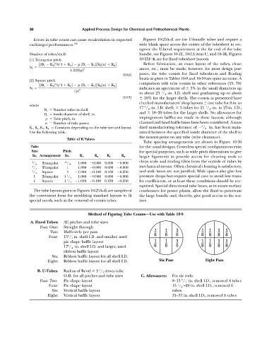
                                                    Method of Figuring Tube Counts—Use with Table 10-9
                       A. Fixed Tubes:  All pitches and tube sizes
                            Pass: One:  Straight through
                                                                                    1     1    1            1  1    1  1
                                 Two:   Half-circle per pass                        –     –    –            –  –    –  –
                                Four:   15 / 4 in. shell I.D. and smaller, used     6     6    6            8  8    8  8
                                          1
                                        pie shape baffle layout                     1     1    1            1  1    1  1
                                                                                                                       –
                                                                                                            –
                                                                                          –
                                                                                                                    –
                                                                                               –
                                                                                    –
                                                                                                               –
                                          1
                                        17 / 4 in. shell I.D. and larger, used      6     6    6            8  8    8  8
                                        ribbon baffle layout
                                  Six:  Ribbon baffle layout for all shell I.D.
                                Eight:  Ribbon baffle layout for all shell I.D.        Six Pass               Eight Pass
                                                         1
                           B. U-Tubes:  Radius of Bend   2  / 2 times tube
                                        O.D. for all pitches and tube sizes   C. Allowances:  For tie rods:
                            Pass: Two:  Pie shape layout                                     8—13  / 4 in. shell I.D., removed 4 tubes
                                                                                                  1
                                                                                                1
                                Four:   Pie shape layout                                     15  / 4 —29 in. shell I.D., removed 6
                                  Six:  Vertical baffle layout                               tubes
                                Eight:  Vertical baffle layout                               31—37 in. shell I.D., removed 8 tubes
   41   42   43   44   45   46   47   48   49   50   51