
Page 44 - Applied Process Design For Chemical And Petrochemical Plants Volume III
P. 44
66131_Ludwig_CH10A 5/30/2001 4:08 PM Page 34
34 Applied Process Design for Chemical and Petrochemical Plants
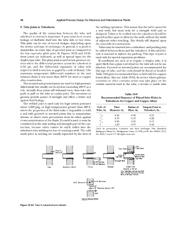
8. Tube Joints in Tubesheets the welding operation. This means that the weld cannot be
a seal weld, but must truly be a strength weld and so
The quality of the connection between the tube and designed. Tubes to be welded into the tubesheet should be
tubesheet is extremely important. A poor joint here means spaced farther apart to allow for the weld, without the welds
leakage of shell-side fluid into the tube side or vice versa. of adjacent tubes touching. The details will depend upon
This joint can be one of several designs, depending upon the materials of construction.
the service and type of exchanger. In general, it is good to Tubes may be inserted into a tubesheet, and packing may
standardize on some type of grooved joint as compared to be added between them and the tubesheet. A threaded fer-
the less expensive plain joint. In Figures 10-23 and 10-24, rule is inserted to tighten the packing. This type of joint is
these joints are indicated, as well as special types for the used only for special expansion problems.
duplex-type tube. The plain joint is used in low-pressure ser- If conditions are such as to require a duplex tube, it is
vices where the differential pressure across the tubesheet is quite likely that a plain end detail for the tube will not be sat-
5—50 psi, and the differential expansion of tubes with isfactory. Grooved or serrated joints are recommended for
respect to shell is very low, as gaged by a rule of thumb. The this type of tube, and the ends should be flared or beaded.
maximum temperature differential anywhere in the unit Table 10-8 gives recommended flare or bell radii for copper-
between fluids is not more than 200°F for steel or copper based alloys. Also see Table 10-8A. In service where galvanic
alloy construction. corrosion or other corrosive action may take place on the
The serrated and grooved joints are used for high-pressure outside material used in the tube, a ferrule of inside tube
differentials but usually not in services exceeding 200°F as a
rule. Actually these joints will withstand more than twice the
push or pull on the tube as a plain joint. The serrations or Table 10-8
grooves provide points of strength and effect a better seal Recommended Diameter of Flared Inlet Holes in
against fluid leakage. Tubesheets for Copper and Copper Alloys
The welded joint is used only for high system pressures
above 1,000 psig, or high temperatures greater than 300°F, O.D. of Flare Radius of Tangent Point to
where the properties of the fluid make it impossible to hold Tube, In. Diameter, In. Flare, In. Tubesheet, In.
a seal with grooved or serrated joints due to temperature
1 0.60 0.38 0.21
/ 2
stresses or where extra precautions must be taken against 5
/ 8 0.75 0.47 0.26
cross-contamination of the fluids. If a weld is used, it must be 3
/ 4 0.90 0.56 0.31
considered as the only sealing and strength part of the con- 1 1.20 0.75 0.42
nection, because tubes cannot be safely rolled into the
Used by permission: Condenser and Heat Exchanger Tube Handbook,
tubesheet after welding for fear of cracking a weld. The rolls Bridgeport Brass Co., Bridgeport, Conn. © 1954, p.148. See TEMA [107],
made prior to welding are usually separated by the heat of Par. RCB 7.4 and 7.5. All rights reserved.
Figure 10-24. Tube to tubesheet joint details.